


 live:657551456


-
Purpose
BTSClient8.0 is based on BTSClient7.6.0 and a brand new version, it has better performance and will replace 7.6.0 gradually. This document targets Neware users, to help them get to know the installation and operation of BTSClient8.0.
-
Hardware and software connection
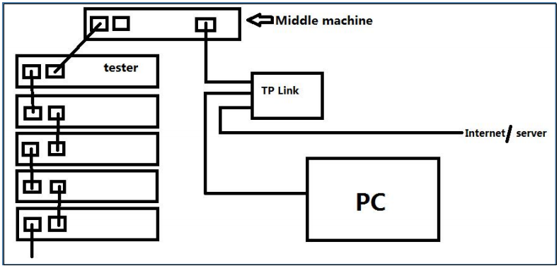
1. The connection diagram of one device:
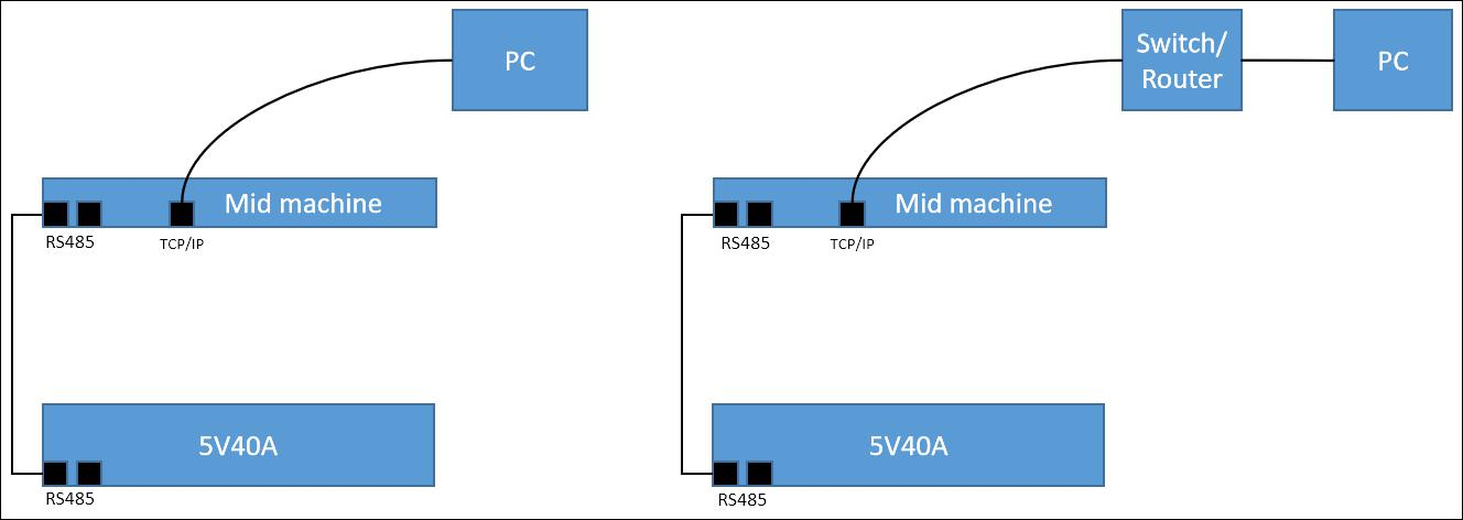
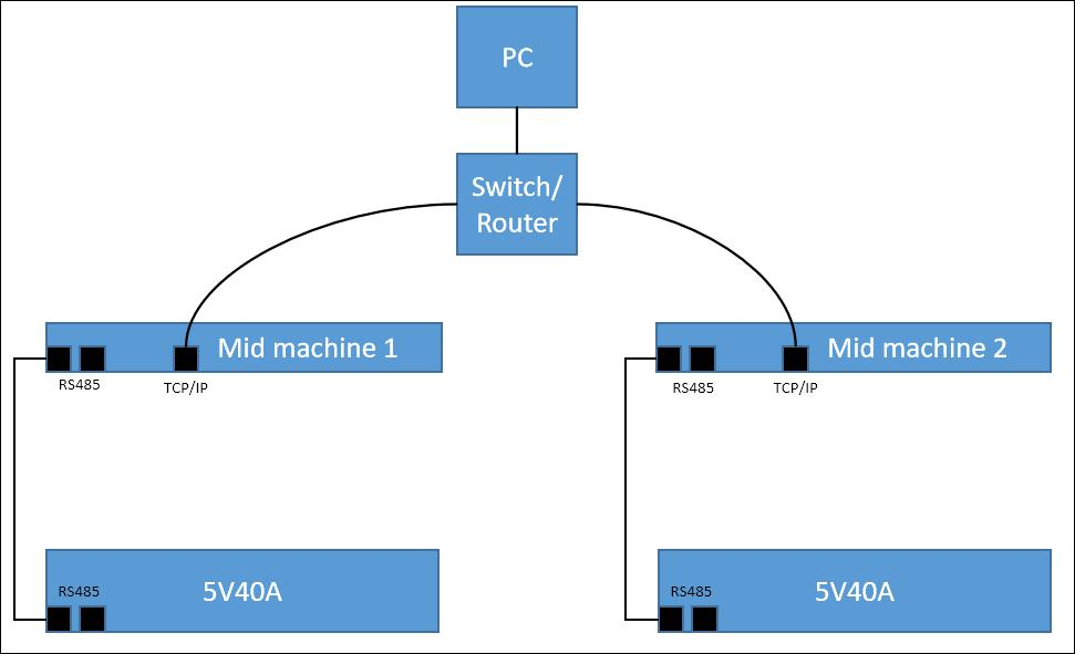
2. The connection diagram of multiple devices:
-
Content Description
BTSClient8.0 mainly introduced the installation and uninstall of client software, the connection between software and server, and how to connect with computer after software successful installation. What’s more, it also introduces the operation of each function, such as battery sorting, auxiliaries mapping setting and trans-middle machine mapping realizing,etc.
-
Introduction
BTSClient8.0 is the brand new client of Neware battery test system, it’s based on BTS7 and evenbetter. BTS software is based on C/S structure and database(mysql), a typical diagram
Looks like the picture below.
-
Installation of client software
Only one client software is allowed in one computer for the operation efficiency.
Notes: The FAT file system has a high probability of errors during power failure. When installing software, you should install it into NTFS file system.Otherwise, when the power is cut off or the system is shut down abnormally, the entire directory may be wrong, which may cause errors in the steps files, system files or data files.View NTFS system property display, please refer to the figure below.
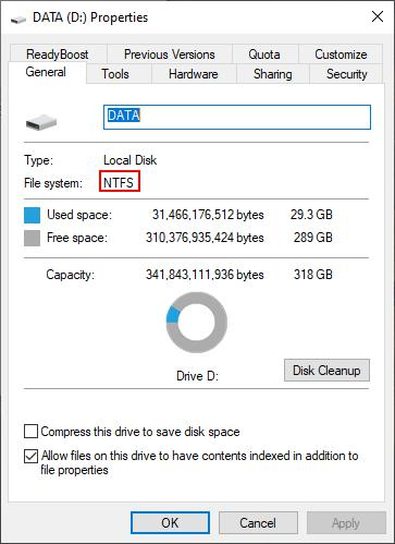
Figure 3.2.1 View file system type
Client software is green version of RAR,double click “BTS.exe” to use it after decompressing.
Notes: Net environment is required when running client software, please install “Microsoft .NET Framework 4.5.1.exe” firstly. If not the client can not be started.
-
Software Requirements
Items
Configuration
CPU
Intel i3 or better
Memory
4GB minimum, 8GB+ better
Hard drive
200GB+
File system
NTFS
OS
Microsoft Windows 7 + 64 bit
Interfaces
USB, Ethernet
-
BTS Software Features
1. C/S structure, base on TCP/IP and database.
2. Multi-user supported.
3. User friendly design.
4. Powerful test process control.
5. Flexible and complex programming test solutions.
6. Perfectly realize battery sorting, matching, and curve comparison.
-
Verify the correct installation of server
After finishing installation, you need to verify whether the server is installed correctly or not, the operations as follows:
1. Click “Control Panel”→ “System and Safety” → “ Management tools”Choose “ Service” to make sure whether “MySQL” and “NEWARE BTS Service” are in the list on the right and started.( Shown in the figure 3.4.1)

Figure3.4.1 Service and application window
2. If there is no “MySQL”or “NEWARE BTS Service” in the list, please uninstall the server and install it again.And reconfirm with the steps above that the server is properly installed and started.
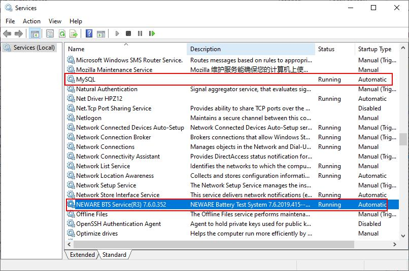
Figure 3.4.2 Start setting window
3. If there is no “MySQL”or “NEWARE BTS Service” in the list, please uninstall the server and install it again.And reconfirm with the steps above that the server is properly installed and started.
4. If you find that the start type of either service is "Manual", please change it to "Auto" as follows. For example, the start type of NEWARE BTS Service is manual(as same as MySQL)
Method 1:
1. Right click “NEWARE BTS Service”,choose “Property”
2. Start type: choose “Auto” (Shown in the figure 3.4.3)
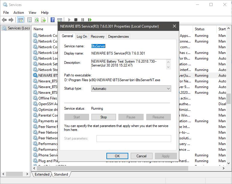
Figure 3.4.3 NEWARE BTS Service start window
Method 2:
1. Open “Running...” from the start menu, enter “msconfig”and click “Enter”.
2. Enter “System configuration utility”. choose“NEWARE BTS Service”in the service, click “Apply”and restart the computer.(Shown in the figure 3.4.4)
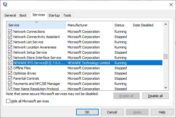
Figure 3.4.4 System configuration utility window
Notes: In Computer Management window. Right click and choose “Stop” to close the running service. It will be needed when manually upgrade the server.
-
Basic functions of software
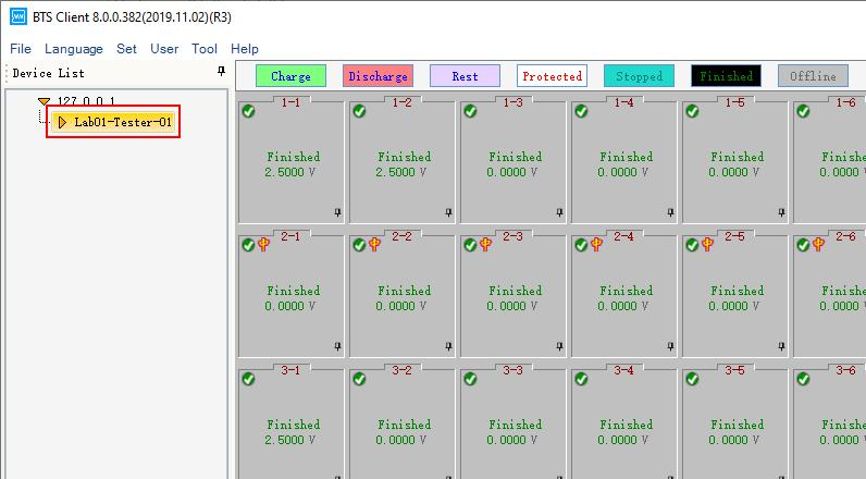
If there is no channels displayed in the client software, it needs to map again.( Client software interface after mapping successfully shown in the figure 3.5.1)
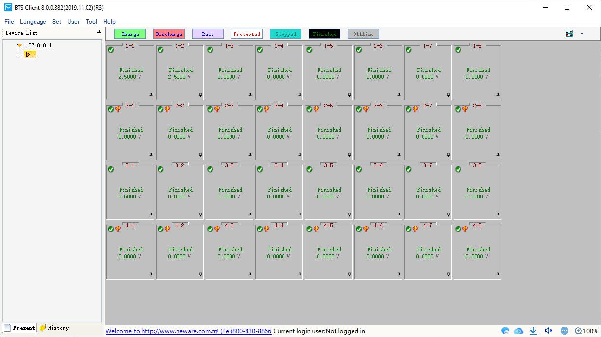
Figure 3.5.1 BTSClient8.0.0 main window
When the software display is minimized, the image of it on taskbar will be hidden. You can find it in the pallet list.You can also drag client software into the quick start bar,which is a common feature of popular software. Notes: You also can choose that minimization software will be displayed in the taskbar through system setting.
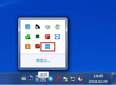
Figure 3.5.2 Software minimize into pallet list
Explanation of Nouns in Step name drop-down list:

Figure 3.5.3
CCD: The channel discharges at constant current, and the battery voltage drops, in which the cut-off voltage and the constant current value must be set. Time, capacity, energy are alternative conditions . It means “or” logically relations among them. The figure above indicates that the battery discharges from the beginning of 1200mA current to the end of the 2.8V.

Figure 3.5.4
CCC: The channel is charged with a constant current value, and the battery voltage is raised. The cut-off voltage and the constant current value must be set. Time, capacity, energy are the conditions of choice, it means “or” logically relations among them. The figure above indicates that the battery charges from the beginning of 1200mA current to the end of the 4.2V.

Figure 3.5.5
Rest: The channel is rest. The step time must be set. The picture above indicates that the channel will rest for 5 minute.
Figure 3.5.6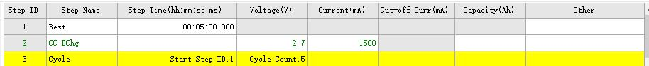
Cycle: Define multiple steps for cycling . The figure above indicates that step 1 or step 2 will be performed 5 times from the first step.

Figure 3.5.7
CC&CVC: When the battery voltage is below the set voltage value, the device charges the battery in a constant current mode until the battery reaches the set constant voltage value and then enters a CV process. The figure above shows that the battery is charged by 1200mA, and the battery enters the CV process at 4.2V, where the voltage remains constant and the current drops slowly until the current goes down to 50mA. Lithium battery charging and CV-Chg to CC-Chg process, the step voltage, current, off current must be set.
Figure 3.5.8
CP-DChg: The channel is equivalent to a battery with a constant power load, and the current in the discharge increases with the decrease of the voltage. The product of current and voltage at 15Neware BTS 8.0 user manual any time is equal to the set power value. As shown above, the battery discharges at constant power of 10W until the end of the 2.8V (assuming that the battery voltage is 5V, the discharge current = 2A, and when the voltage drops to 4V, the current should be 2.5A). The cut-off voltage and power value must be set.

Figure 3.5.9
CP_Chg: Charge according to the setting power, and the current will decrease with the increase of the voltage, because the product of the current and the voltage is always equal to the setting power. As shown above, the battery is charged at a constant power of 4.2W until the voltage becomes 4.2V (assuming the battery voltage is 4V, the current should be 1.05A, and when the voltage rises to 4.2V, the current should be 1A). The cut-off voltage and power must be set in this step.
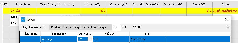
Figure 3.5.10
IF: The insertion of this step in any step is supported, and judge the direction of the step goto by its parameters. As shown below, you can add voltage, step time, environment temp and current, then you can choose Goto to the target step.
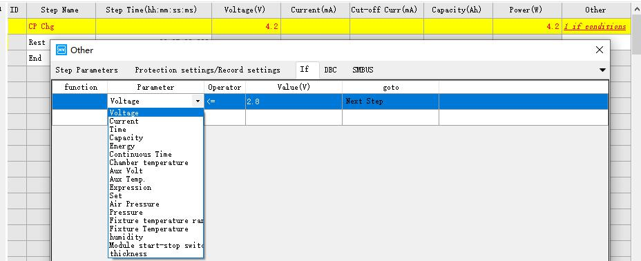
Figure 3.5.11

Figure 3.5.12
CV_DChg: Adopt it when the voltage required to be constant during the discharge, and the discharge current will gradually decrease. As shown above, the battery discharges at the maximum 2000mA (if less than 2000mA, discharges at the actual value, which depends on the battery voltage) until the voltage reaches 3.0V, then the voltage remains constant and the current begins to decrease, and the step will finish when the current falls to 200mA. If the current value is not set in this step, the starting current discharge value may reach the full scale current (depending on the initial voltage). This step requires hardware support.

Figure 3.5.13
CCCV_DChg: Discharge at a constant current value, when the voltage drops to the setting voltage, the voltage remains constant, the current gradually decreases, and then the step comes to the end when it drops to the cut-off current. As shown above, the battery discharges at 1200mA and decreases when voltage reaches by 3.5V, then the step finishes when current drops to 10mA.
-
Process type setting
As shown below, enter the process type you want to use in the left list, click ‘>’、‘>>’and move the type from left list to right. Click ‘<’、‘<<’move it from right list to left. The process type on the right list can choose whether it is a formation or a grading process type.
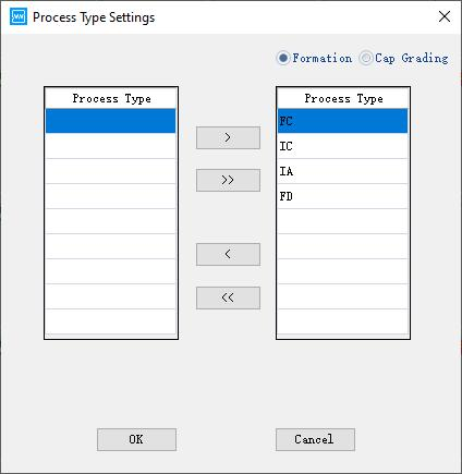
Figure 3.6.3 Process type setting
-
System setting
When the software is used for the first time, the system configuration interface will appear. At other times, you can also call up the system configuration by clicking the menu bar.
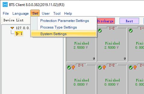
Figure 3.6.4 Choose setting system from menu bar
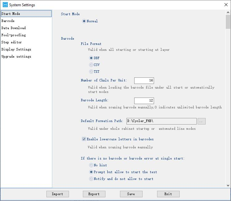
1. Startup mode
After registration, choose the type of startup mode and restart the client software.(Shown in the following figure)
20
2. Barcode
Barcode format, the number of channel, barcode length, default grading category path can be chose under the barcode interface. Meanwhile, you also can confirm whether lowercase are allowed, and whether a single point can start up when there is barcode errors or no barcode.After finishing,click “Save”.(Shown in the following figure)
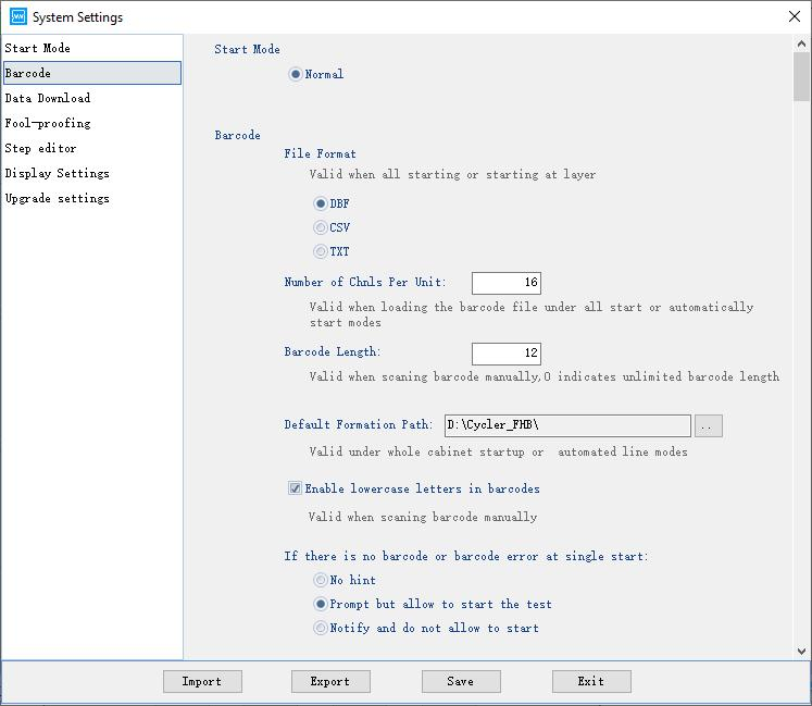
Figure 3.6.6 Barcode setting window
3. Data download
Support to set file format, export mode, export method, etc. After finishing, Click “Save”.(Shown in the following figure)
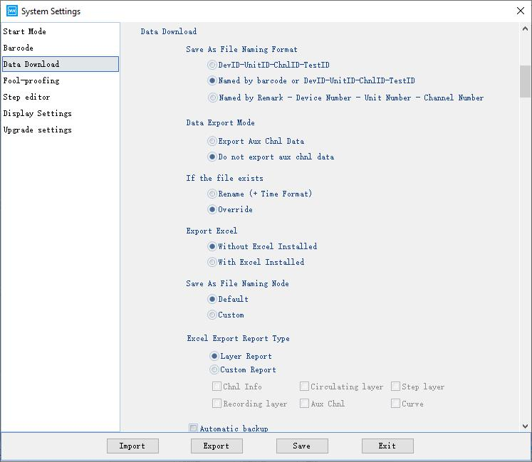
Figure 3.6.7 Data download window
4. Foolproof settings
The startup test channel has functions such as whether the protection prompts or starts, whether passwords is required for the startup test, whether advanced protection parameters are loaded at a single-point startup, whether password verification is required to exit the software,etc. After the foolproof settings are configured, click “Save”.(Shown in the following figure).
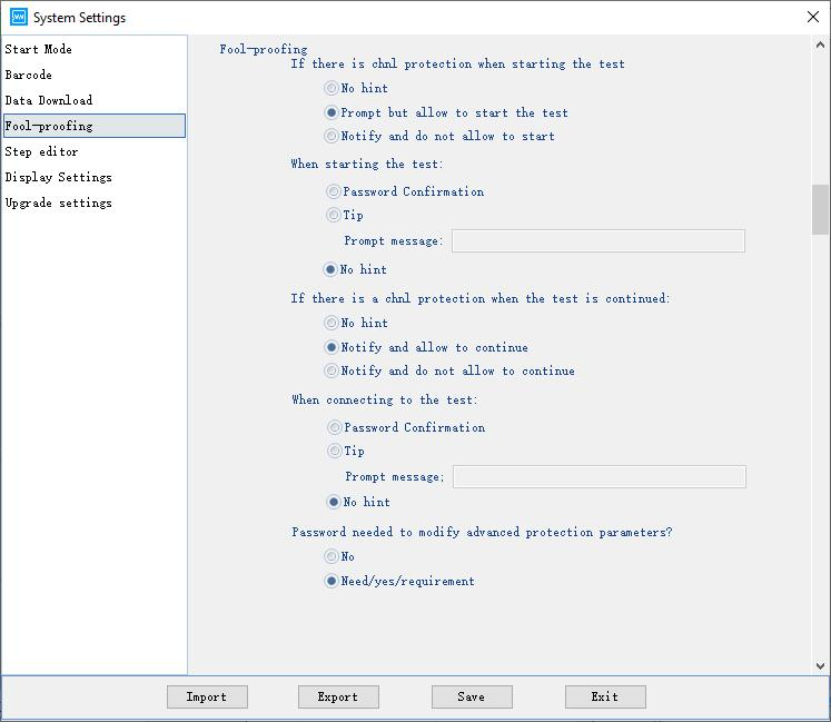
Figure 3.6.8 Foolproof setting window
5. Step edit
It includes following settings: Step parameters, Step type, Required conditions for step parameters, Creator, Batch number, Remarks, Default voltage and current upper and lower limit protection, Default and minimum step interval, Cutoff current, Weather a single step is allowed to edit advanced protection parameters, etc. After finishing, click “Save”.(Shown in the following picture).
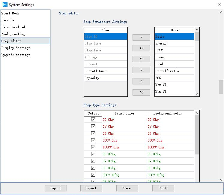
Figure 3.6.9 Step edit window 1
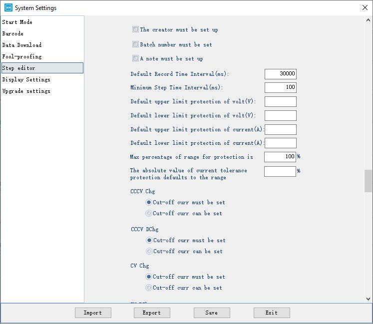
Figure 3.6.10 Step edit window 2
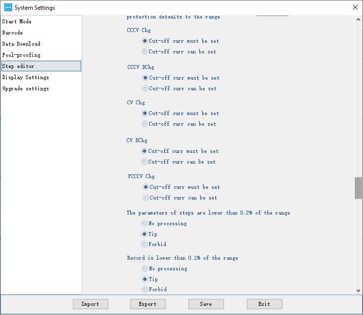
Figure 3.6.11
6. Display setting
It consists of 6 parts : Display setting (Weather display the type of device or not,etc.), View setting (Big image and small image,List,Sorting,etc.), Channel number display per line (Be used when click fixtures), Channel dividing line, Right-click menu function, Channel colour. After finishing, click “Save”. (Shown in the following picture).
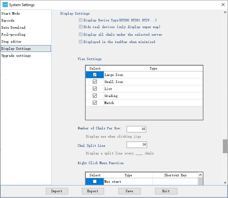
Figure 3.6.12 Display setting window
-
Modify passwords
Users can modify the passwords of device. Modify instruction:
Click “User”→ “ Modify passwords”, after entering your original passwords, it will require you to enter your new passwords. (Shown in the following figure)
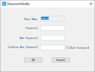
Figure3.7.3 Change password window
-
User logout
Users can log out the present user account of device. Logout instruction:
Click “User”--> “User logout”. When the prompt dialog appears, click “OK”. The user account logs out successfully. If you want to operate, you should login again.
-
User management
If the currently logged-in user is an administrator, you can add, delete, and configure permissions for ordinary users. Manage instruction:
Click “ User”--> “User management”(Shown in the following figure)
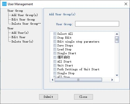
Figure3.7.4 User management
1. Add new user group: configure the permissions for new user group.(Shown in the following figure)
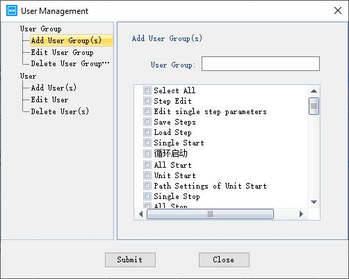
Figure 3.7.5 Permissions configuration
2. Modify user group: Select the user group you want to modify, choose or cancel the permissions you do not need, then click “Submit”. (Shown in the following figure)
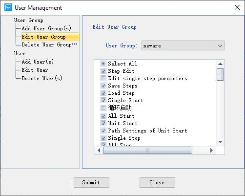
Figure 3.7.6 Permissions modify
3. Delete user group: Select the user group you want to delete and click “ Submit”.(Shown in the following figure)
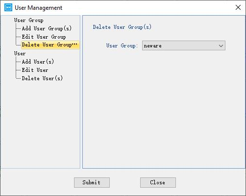
Figure 3.7.7 Delete users window
4. Add users: Select the user group for new user, enter the user name, password and click “Submit”.(Shown in the following figure)
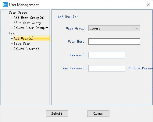
Figure3.7.8 Add users window
5. Modify users: Choose user group name and user name, enter new passwords, click “Submit”. (Shown in the following figure)
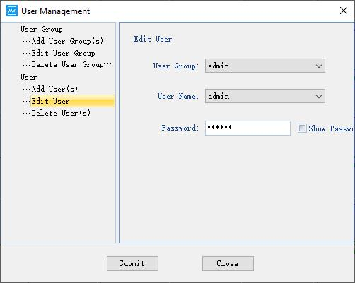
Figure 3.7.9 Modify user
6. Delete users: Choose user group name and user name, click “Submit”.(Shown in the following figure)
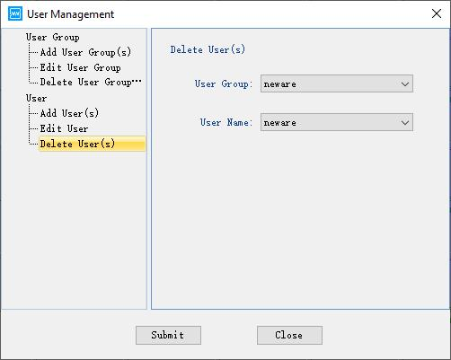
Figure 3.7.10 Delete users window
-
Language switching
Client software supports Simplified Chinese,Traditional Chinese, English, Korean switching. Switching instruction:
Click “Menu” --> “Language”choose the language you want.(Shown in the following figure)
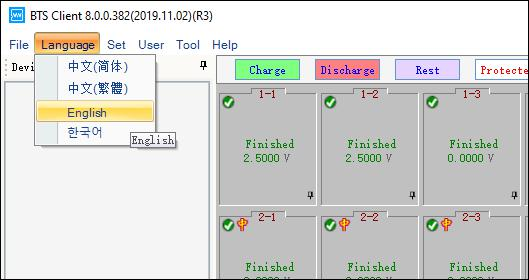
Figure 3.8.1 Multilingual switching 多语言切换
-
Tools
You can find other software of BTS series through “Tools”.Such as BTSDA, Offline step editor,Download log software.(Shown in the following figure)
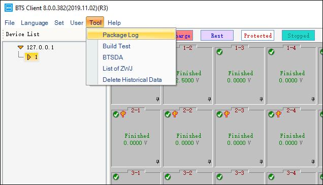
Figure 3.9.1 Tools
1. Download log
Choose “Download log” in “Tools”,you can choose server IP, time range of log, save path of log. The content of log includes client software log and server log.(Shown in the following figure).
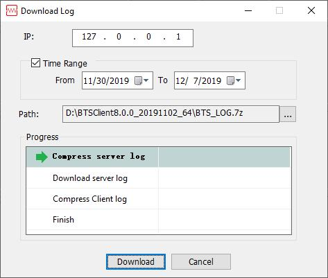
Figure 3.9.1 Download log window
2. Step editor
Choose “Step editor”in “Tools”or double click “BuildTest.exe” to start up offline step editing function.(Shown in the following figure)
Figure 3.9.1 Offline step editor window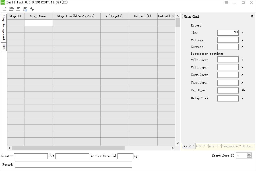
Notes: For detailed instructions on how to use the step editor, please see the BuildTest user manual.
3. BTSDA
a. Right click at channel data, you can open BTSDA window.(Shown in the following figure).
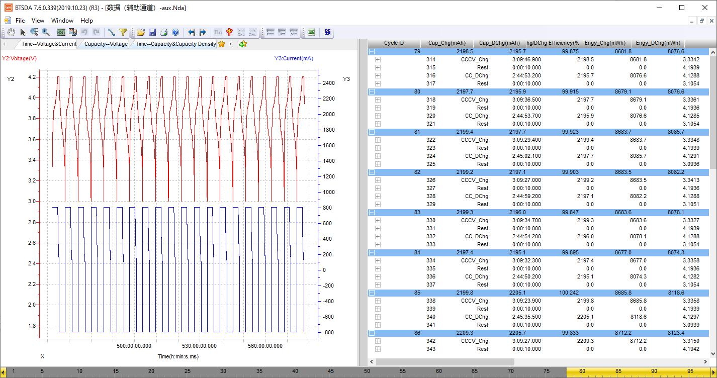
Figure 3.9.1 BTSDA window
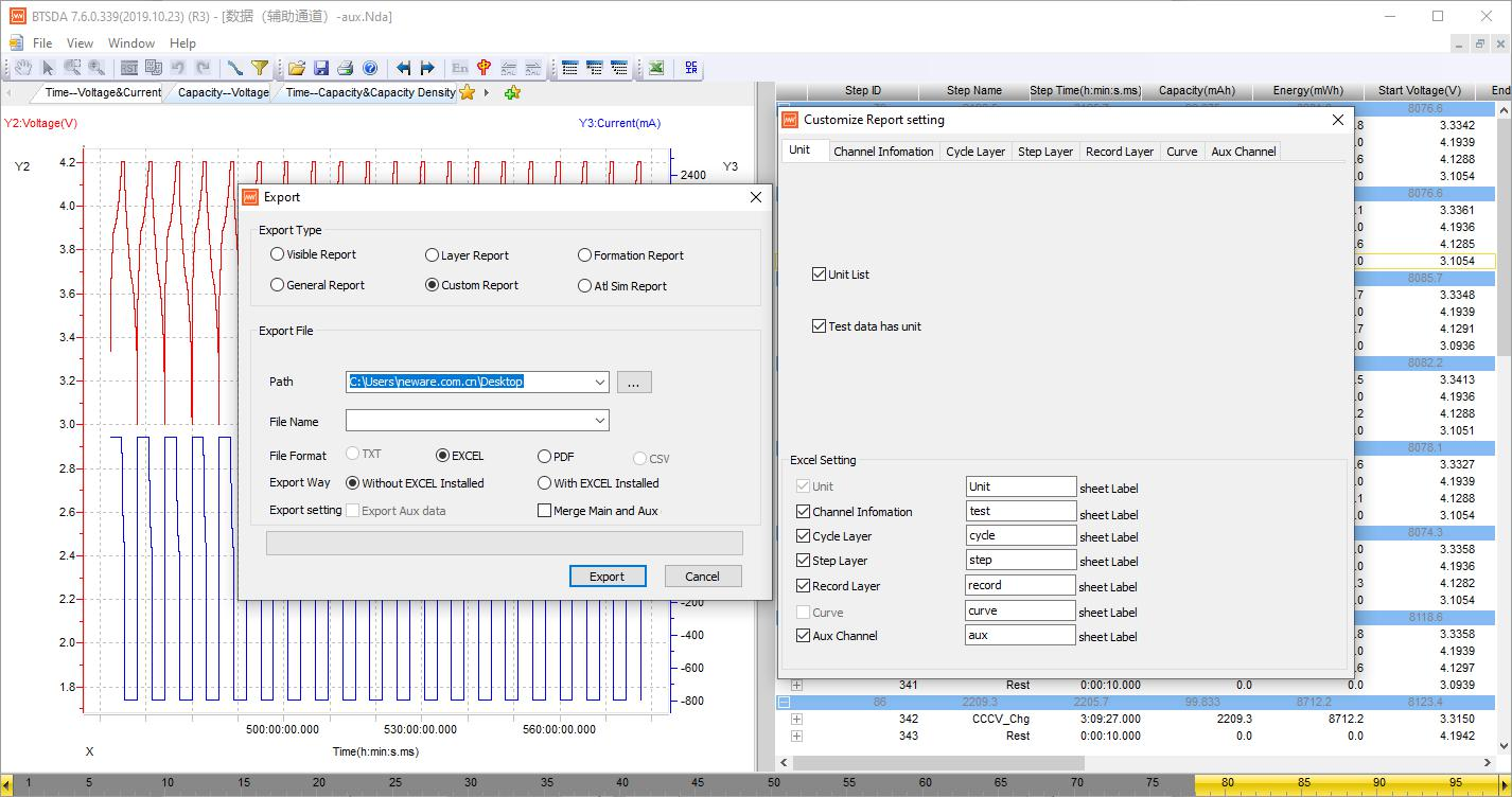
b. The method to export data report is shown in the following figure.
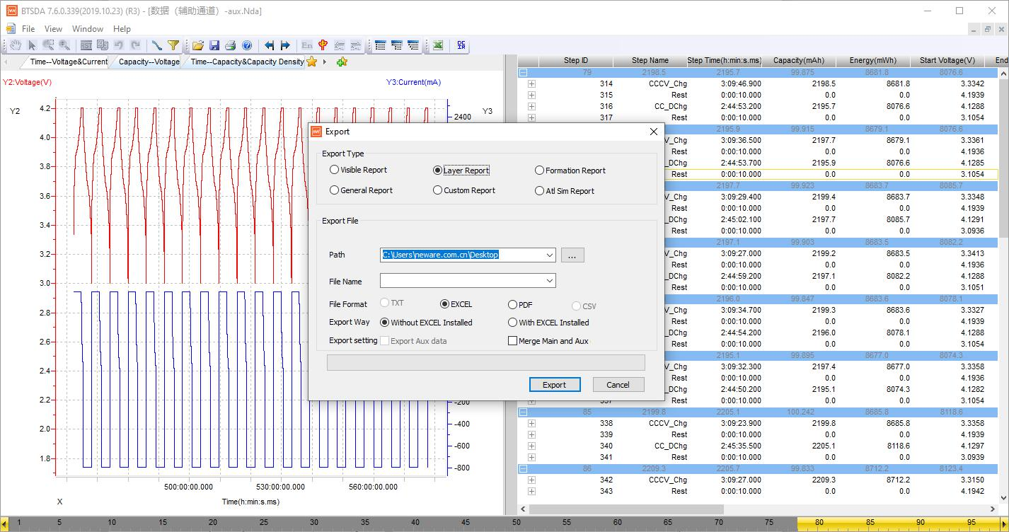
Figure 3.9.1 Export data report window
c. Data report customized parameters setting(Shown in the figure).
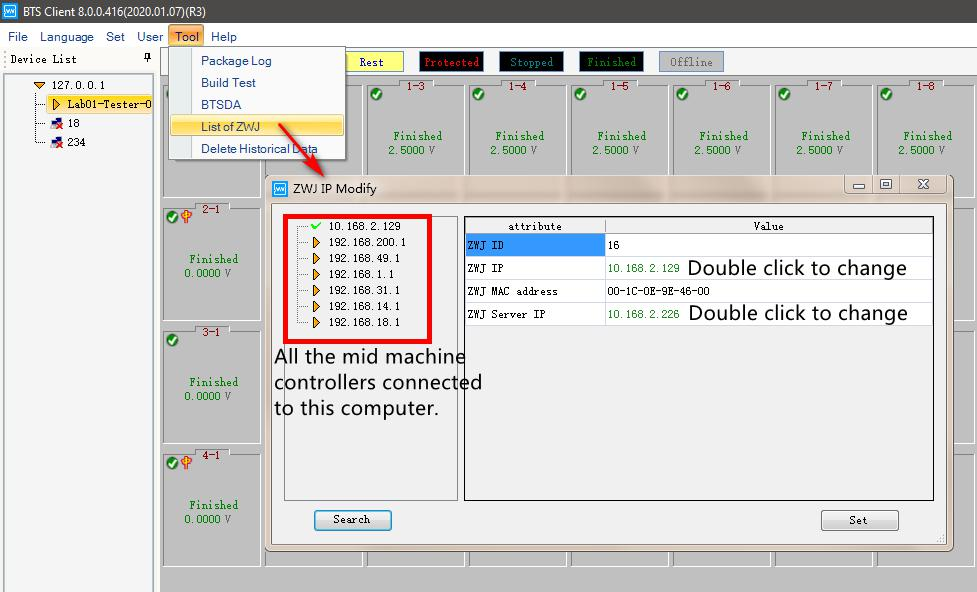
4. Middle machine list
Open middle machine list to automatically search for the online middle machine, you also can modify middle machine IP and server address.(Shown in the figure).
5. Delete historical data
Delete data by setting time range.(Shown in the figure)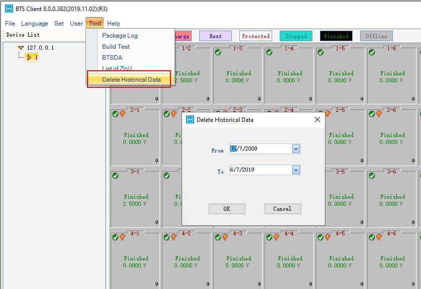
-
Device list
1. Add server
Default local service:127.0.0.1. If you want to access other services,select any service IP and right
click “Add server”, you also can add and modify notes on it.(Shown in the following figure)
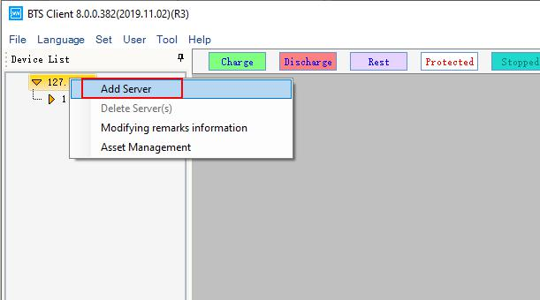
Figure 3.10.1 Add server
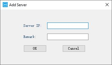
Figure 3.10.2 Add server
Notes: Adding server is not allowed in the mode of automatic production line.
Move the mouse cursor at server IP, you can see the information of server version.(Shown in the following figure)
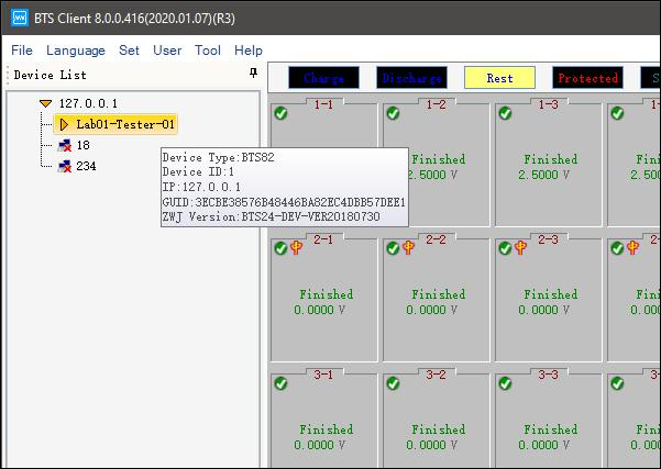
Figure 3.10.3 Information of server version
2. Delete offline device
image will be displayed after the device offline.If you do not wants to display them, you can delete the offline devices. Delete instruction:
1. Choose offline devices in the device list. 2. Right click and choose “Delete”or “Delete all offline devices”.
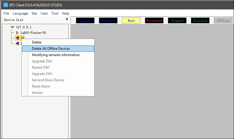
Notes: Online devices will not be deleted.
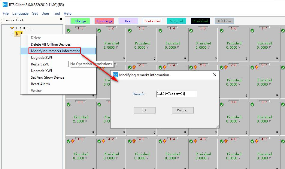
3. Modify notes/remarksChoose the middle machine firstly , right click to modify notes.(Shown in the figure)
4. Update middle machine
Middle machine can be updated by downloading the upgrade package through client software. Update instruction:
A. Choose the middle machine in the device list.
B. Right click and choose “Update middle machine”,entern the user name and passwords.
C. Choose upgrade file in updating window,click “Update”. 4. After finishing, upgrading complete dialog will appear, close it.
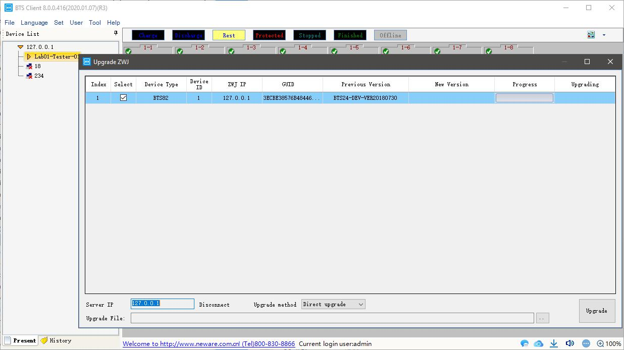
Figure 3.10.4 Update middle machine
Notes: Offline devices are not allowed to update. Please contact Neware engineers for firmware update. Please don’t use the online firmware, it might cause problems to the hardware.
If you want to update several middle machines at one time, right click in updating window.
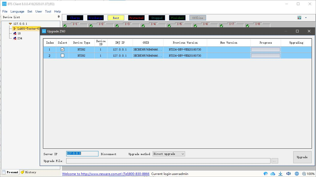
Figure 3.10.5 Upgrade several middle machines
5. Restart middle machine
The median machine can be sent a restart command through the client software. Restart instruction:
1. Choose device in device list
2. Right click and choose “Restart middle machine”.
6. Upgrade low machine
Low machine can be upgraded by upgrading package through client software. Upgrade instruction:
1. Choose middle machine in device list.
2. Right click and choose “Upgrade low machine”.
3. Choose upgrade files and low machine and click “Updrade”.
4. Upgrading finishing dialog will appear when finishing,close it.
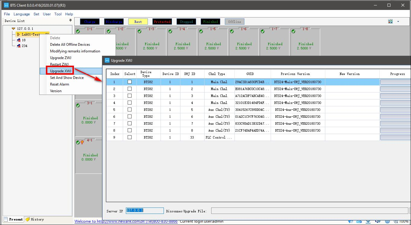
Figure 3.10.7 Upgrade low machine
Notes: Offline devices are not allowed to upgraded.Please contact Neware engineers for firmware update. Please don’t use the online firmware, it might cause problems to the hardware.
If you want to upgrade several low machines at one time,right click in upgrading window, click “Display all devices”and choose low machines you want to update and updating files, click “Upgrade”.(Shown in the following figure)
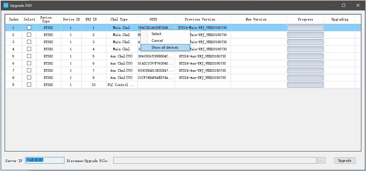
Figure 3.10.8 Upgrade several low machine
7. Set and display middle machine and low machine
You can see the version and modify the number of middle machine and low machine from client software.
Instruction:
1. Choose middle machine in device list. 2. Right click and click “Set and display middle machine and low machine”.
3. Enter new number of machine,click “Setting”.
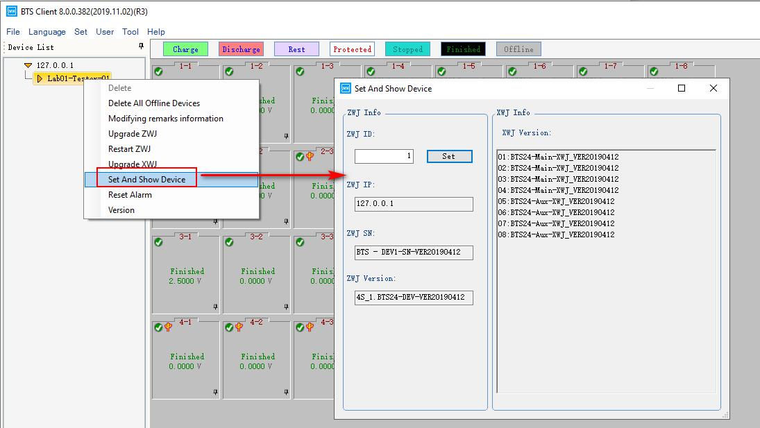
Figure 3.10.9 Setting and display middle machine and low machine
8. Sound-light alarm reset
If the device is equipped with a buzzer, the buzzer will alarm when the channel is protected. At
this time, the alarm can be reset by the sound and light alarm reset. Reset instruction:
1. Choose the channel or device
2. Click “Sound-light alarm reset”.
9. Version information
You can view the version formation of each middle machine and low machine.
Instruction:
1. Choose middle machine in device list.
2. Right click and choose “Version information”.
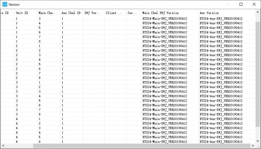
Figure 3.10.10 Version information
-
Channel interface
1. Channel colour setting
Channel colour consists of background colour and foreground colour(font colour),you can change the colour
according your preferences.
a. Channel background colour setting:
Click colour box and choose the colour you want. For example, Click “Charge” the color box will appear and
choose the colour. Right click and choose “ Withdraw” the colour will become default colour. (Shown in the
following figure)
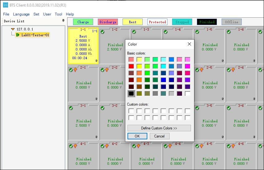
Figure 3.11.1 Set colors of channels in different status
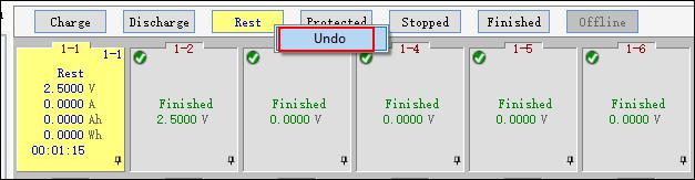
Figure 3.11.2 Right click to restore default colour
b. Font colour setting
The font color needs to be modified in the system display settings.In the system setting,channel colour can be forbidden to modify, which is convenient for unified color management within a company.You also can hid the unset background colour in channel display window.
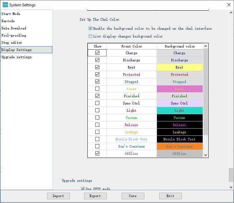
Figure 3.11.2 Foreground colour setting
2. Channel display configuration
a. Channel protection and alarm
Instruction:
Click
 in the right corner of client channel display window. Message window will appear.(Shown in the following figure).
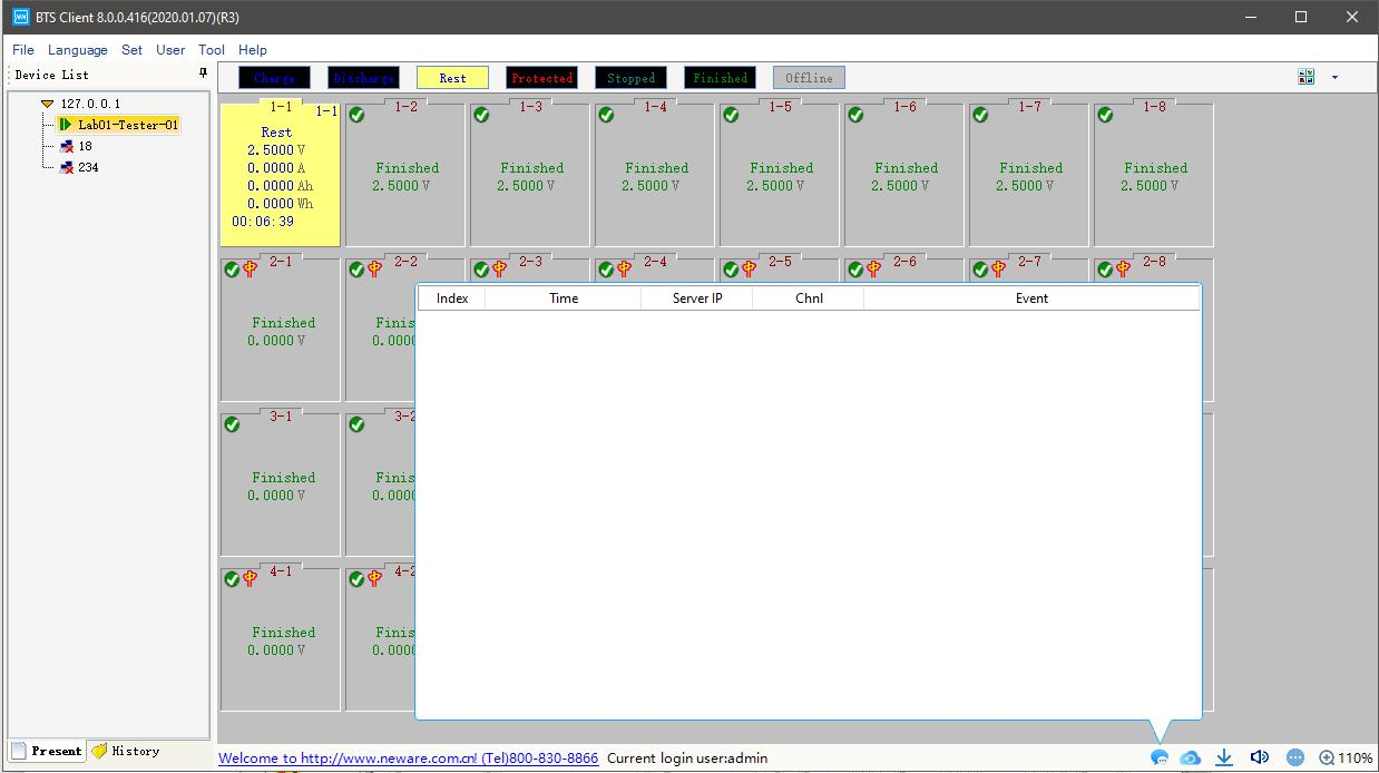
Figure 3.12.1 Message
b. Automatic backup
View the current and historical backup data. You also can add, modify, and delete the data after starting the test.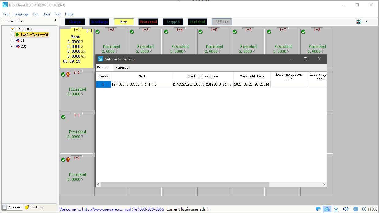
Figure 3.11.2 Automatic backup
c. Data download and view
At the right bottom corner of the BTSClient, click the icon
 , the downloader window will pop up, which looks like the picture below.
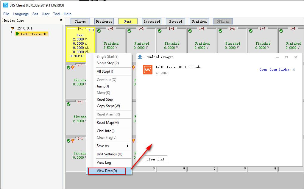
Figure 3.11.3 Data view and download
d. Alarm
At the right bottom corner of the BTSClient, click the icon
 , it will open or close sound alarm, and you can choose alarm available in the following situations.
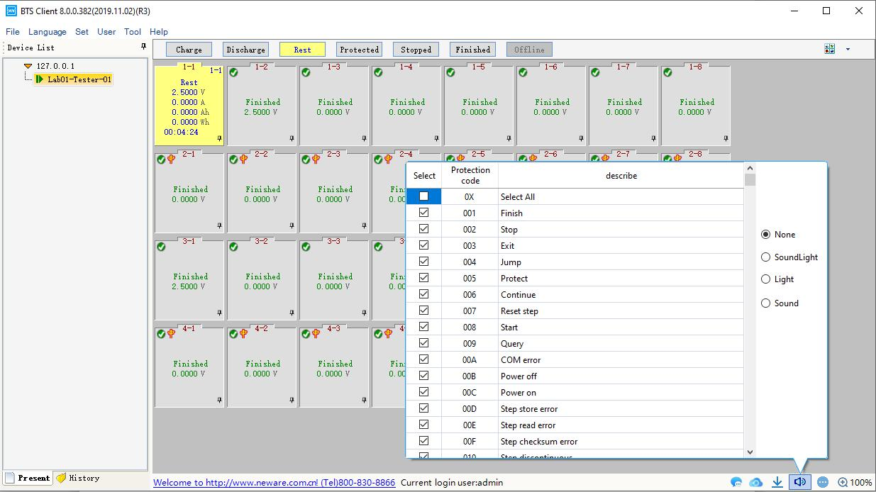
Figure 3.11.4 Alarm settings
e. Channel information display
Operation of ‘large icons’:
When BTS client is in ‘large icons’view, right click the icon
 at the UI bottom right, a window will pop up which looks like below:
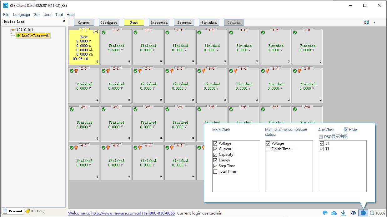
Figure 3.11.5 Display/view settings
Operation of ‘small icons’:
When BTS client is in ‘small icons’view, right click the icon
 at the UI bottom right, a window will pop up which looks like below:
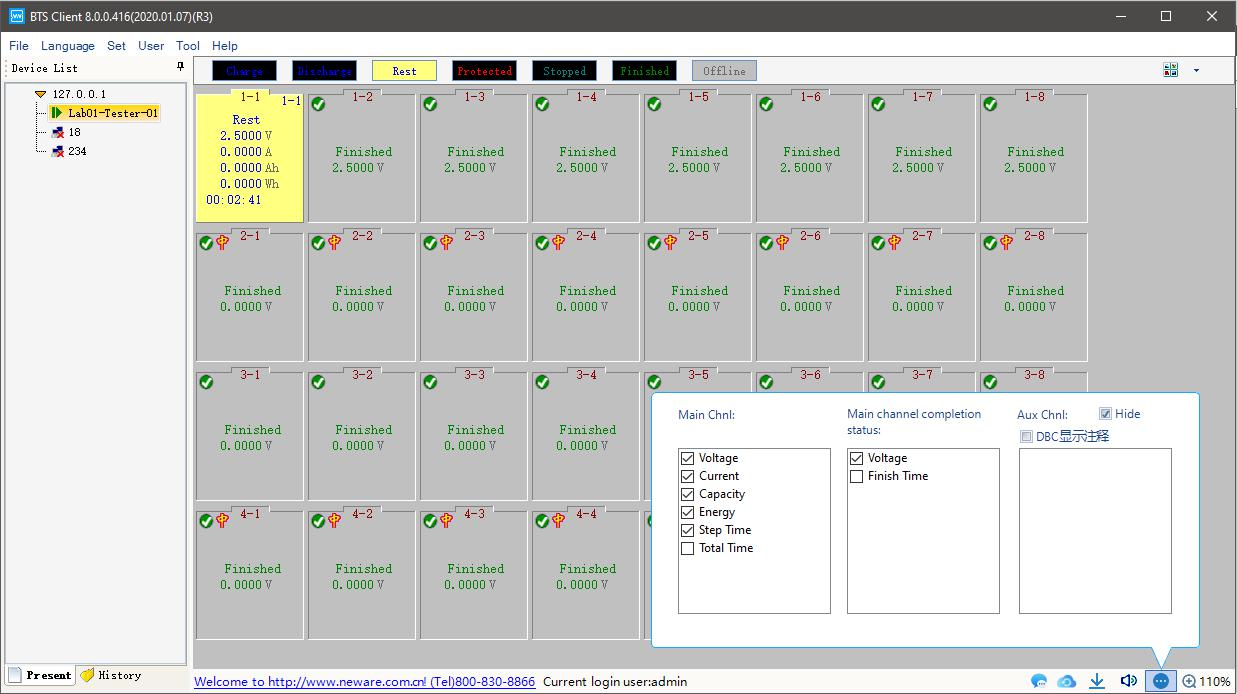
Figure 3.11.6 Configuration Icon shows more available fields
f. Font and channel/battery size:
Click the right bottom corner icon , then you can zoom in/out the font and channel/battery size of the UI.
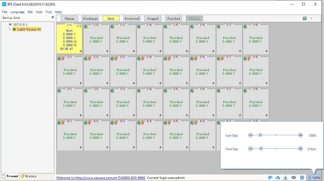
Figure 3.11.7 User interface Zoom in and out
Software defaults to click the BTS number in the BTS list, right side shows all channels for the corresponding equipment, channels will not be displayed if click on other nodes,if multiple BTS need to be started uniformly, It can be selected in the system configuration interface“Displays all channels under the server after that, click on the server node, all channels under this server are displayed on the right side. As shown in figure below.
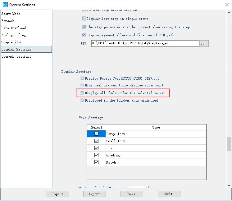
Figure 3.11.8 Configuration of show all the channels in one place
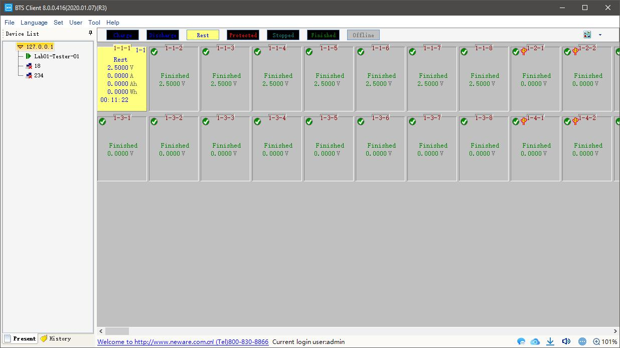
Figure 3.11.9 Show all the channels in one place
3. Display Interface
As shown in figure below, switch to large icon, small icon, list, sorting interfaces respectively through the button in up-right corner.
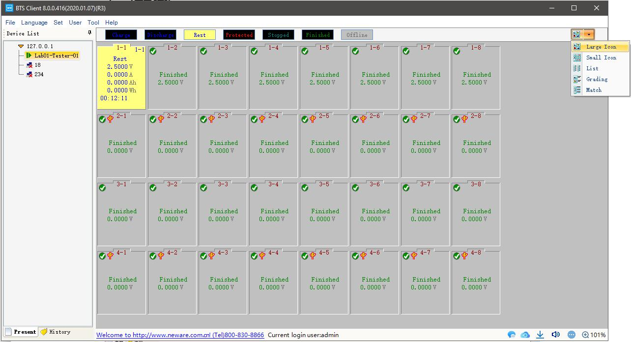
Figure 3.11.10 Switch between different views
-
Right-click the channel interface
Right-click the channel display area, if the option is grayed out, user needs to log in first, then corresponding operation can be carried out.
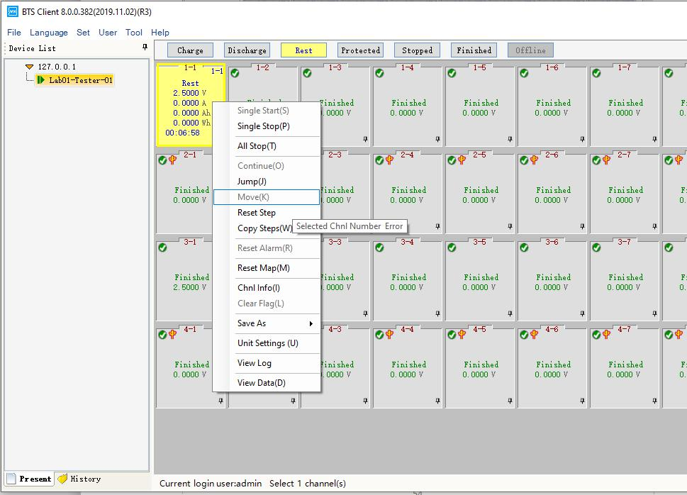
Figure 3.12.1 Right click and the menu of channels
when channel is offline,the background color of the channel changes to the gray, as shown in figure below.
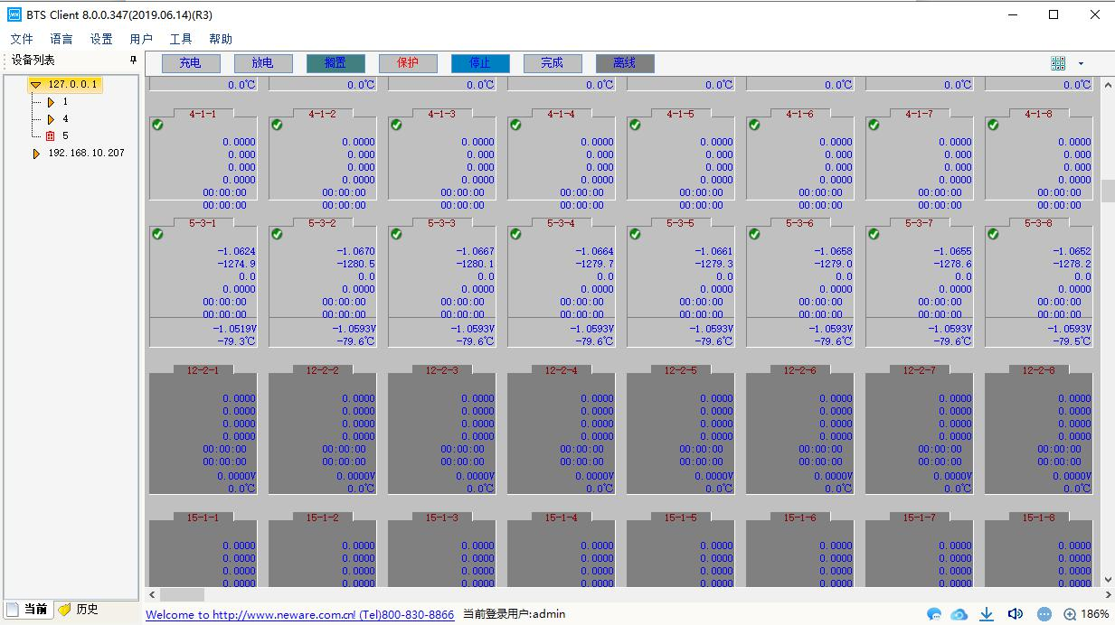
Figure 3.12.2 Show offline channels
For functions that cannot be operated in the right-click menu, hovering mouse cursor over a corresponding position,the corresponding reason will pop up,as shown in figure below.
Figure 3.12.3 For unavailable items, system will prompt you why you can work with it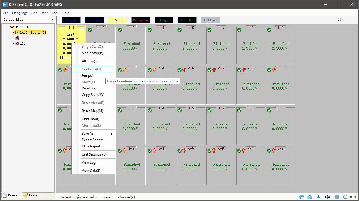
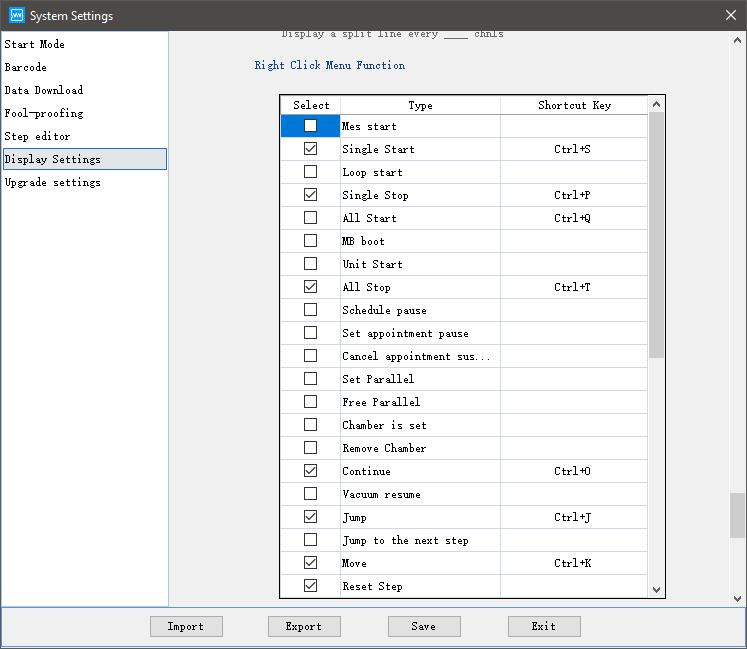
Figure 3.12.4 Choose what items will be shown in the right menu
1. single start
When a “single start” operation is required,the operation is as follows
Select the channel to be operated→right-click→“single start” Work step, recording condition, safety protection etc can be set (as shown in figure below).
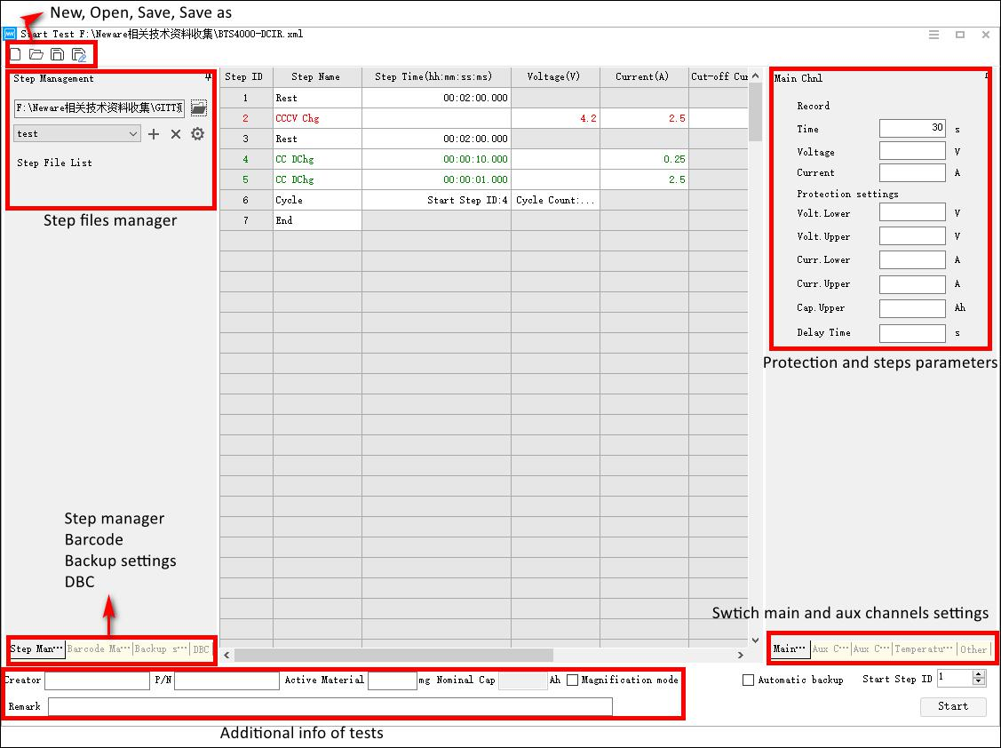
Figure 3.12.5 Test profile manage and create interface
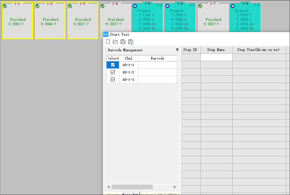
Select the channel to input barcode→Right click→“single start”
Click barcode management interface to input barcode, as shown in figure below.
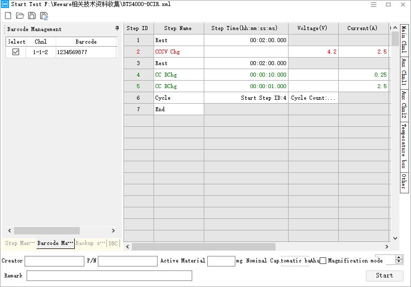
Figure 3.12.6 Barcode input user interface
Backup Settings interface
Operation method→Select the channel to be tested, right click start→click backup setting
perform an automatic backup,as shown in figure below:
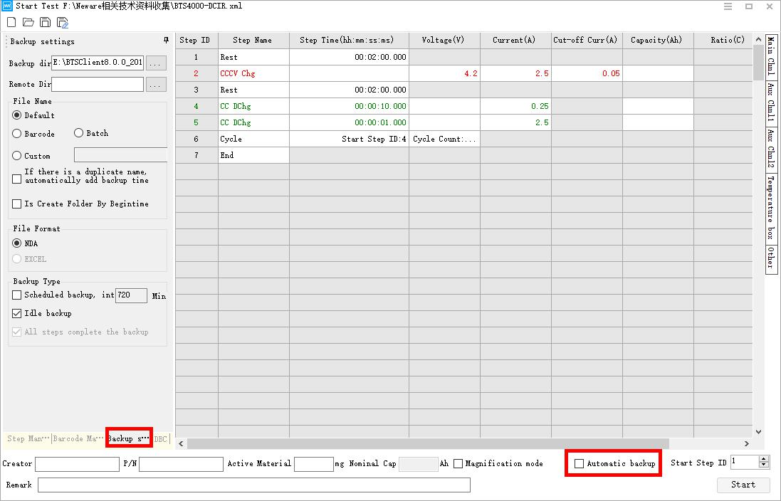
Figure 3.12.7 Backup setting interface
2. single stop
When the working steps of single or multiple channels need to be reset,
Select single or multiple channels→right click→“single stop"
3. Start up test by row/layer
If we need to start up tests for more than 1 channel at the same time, say start
up tests on a row or a layer. We can make it by doing as following way.
1) Right click →“unit start”;
2) Here the unit start window popped up, and after we’ve set up the profile path, sample frequency, safety settings, then click ‘ok’button.
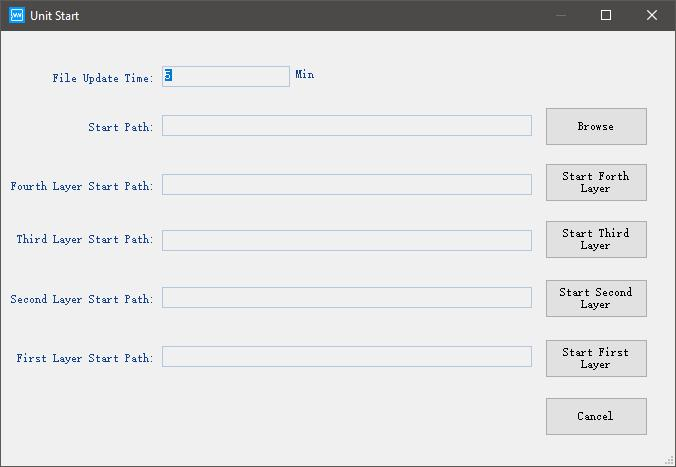
Figure 3.12.8 Start test on a whole layer/unit
4. All stop
“all stop” option needs to be executed when all channels test need to be stopped at the same time,operation is as follows: right click in the channel status display area.In this moment, All channels that are being tested will be in a "stop" state.
Appointed pause
When user wants the channel to stop running automatically after the work step has completed, It can be realized through “appointed pause”
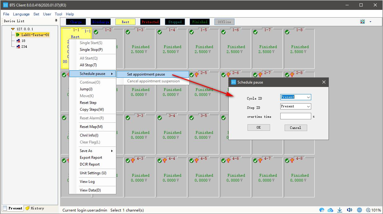
Figure 3.12.9 Set appointment pause
operation is as follows
1. Select the channel which need appointed pause, (A channel marked with a yellow border),as
shown in the figure
2. right click→“set appointed pause”→“Pop up the appointed pause interface”
3. right click→“set appointed pause”→“Pop up the cancel appointed pause interface”
After setting the appointment pause, The corresponding channel will display a pause mark
 , indicates that the current cycle will be paused or the specified cycle will be paused after completion; When the number appears in the right corner of the pause mark,represents the pause after the completion of the current work step or specify pause after the work step is completed,the number represents the serial number of the work step.When the pause Settings need to be unset,select the option to cancel the appointment pause in the right-click menu.the mark of appointed pause on the channel will disappear;After the current work step or cycle is completed “pause”will appear on the channel.
Note: This function only supports BTS82 and above BTS types.
5. Continue/resume test.
Sometimes you did continue/resume operations on the running tests to protect the data from being loss or due to some other reasons. And after that, you can to continue/resume the tests, then you can use this function. Operation: Select the channels need to be ‘continue’, right click and choose ’continue’, then the paused tests will resume and go on.
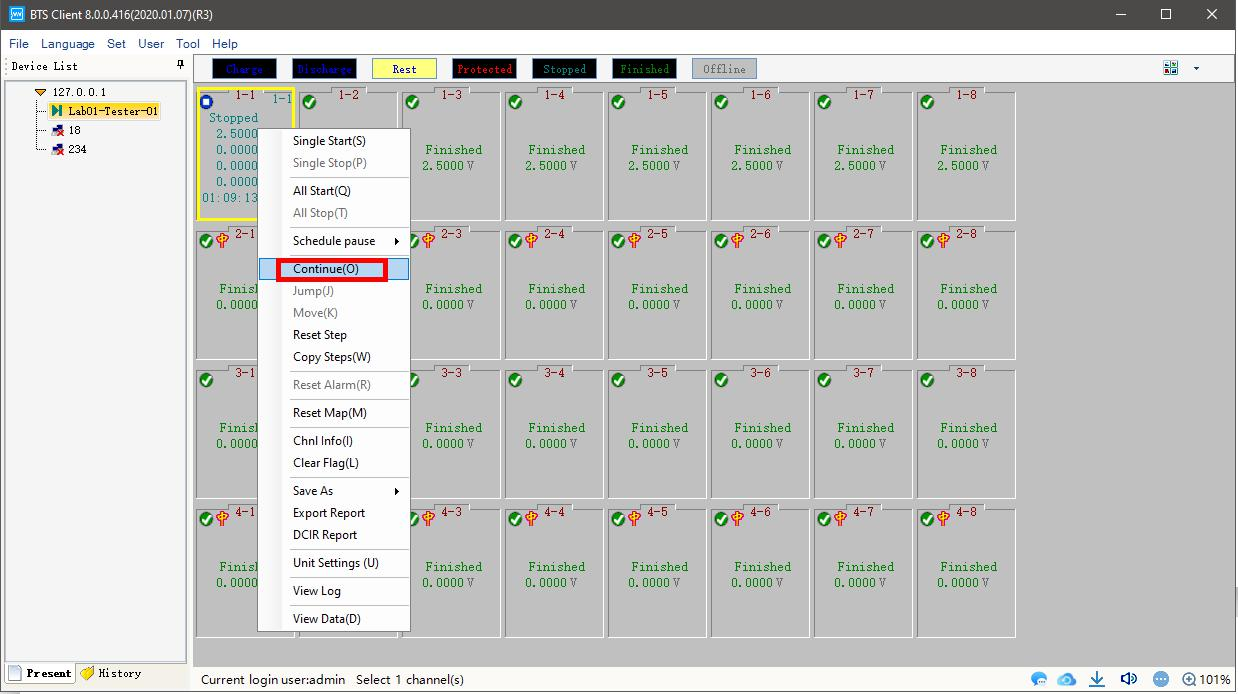
Note: Stop and continue can only be used on channels ongoing, for channels
Finished/completed, this function makes no sense.
6. Jump
When the channel is executing a working step,the current work step can jump to the target work step,This operation maintains the normal continuation of the test data.
Method:
1. Double click the working step,when the working step background turns yellow, it is selected.
2. In the “Jump”interfaces,Fill the required working step number in

, as shown in figure below:
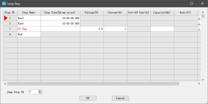
Figure 3.12.10 Steps jump
7. Channels move
Function: Migration of working step parameters and test data from one unfinished test channel
to another completed test channel to continue testing,the purpose is to prevent the failure of
this test due to channel damage. operational approach:
1. Select both channels(test channel,Target channel after migration)
2. Right click→“channels move”;the target channel is not in the working state
Note:this function only support for BTS80 and above BTS types
8. Test profile reset/modify
Function:When the user needs to modify the working step or parameters of the running channel, it can be achieved by resetting the working step
Operation method:
1. Choose the running channel need to modify the test profiles;
2. Right click and choose ‘reset step, then the test profile editor will show up as screenshot below.
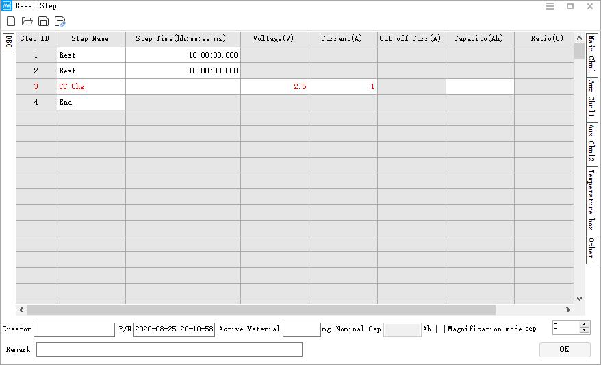
Figure 3.12.11 Reset test steps
9. Bar-code reset
Function: Once the tests already started but operators find the bar-codes were wrong, then they can use bar-code rest to modify the barcodes. Operation steps:
1) Choose the barcodes/channels need to be modified, right click and choose “bar-code rest”, the start test window will pop up, you can reenter or modify the barcodes here.
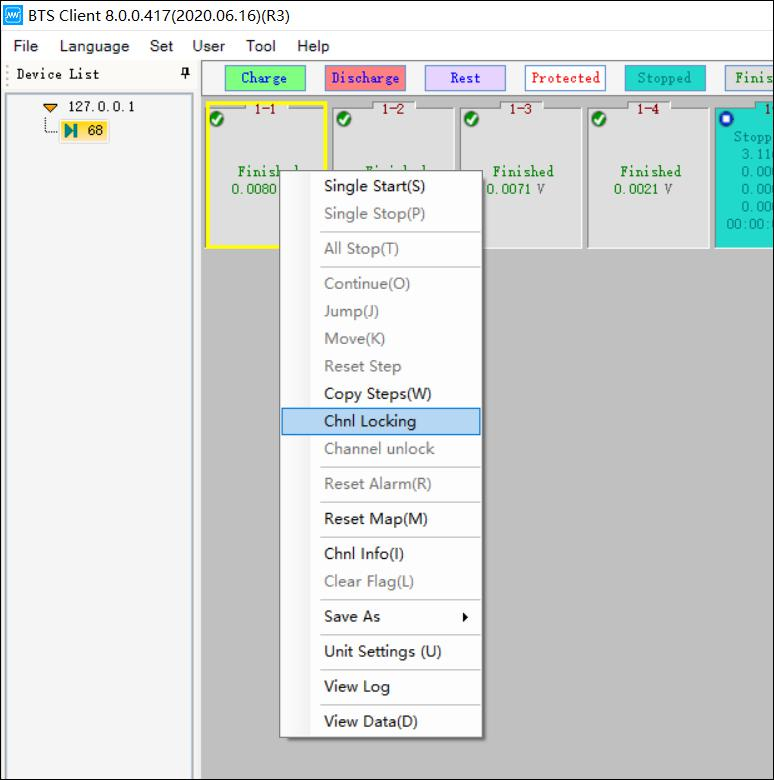
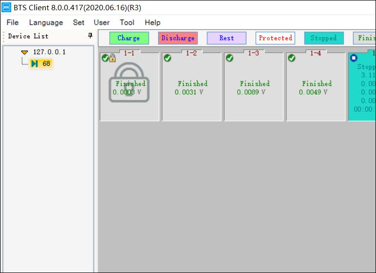
10. Lock/unlock channels
a. For some channels which are running important tests and you just don’t want others to touch them incidentally, then lock them up would be the best option here. Right click on the channels you want to lock and select ‘chnl locking’, then the channels will be locked with an icon
 . Pretty useful, right?
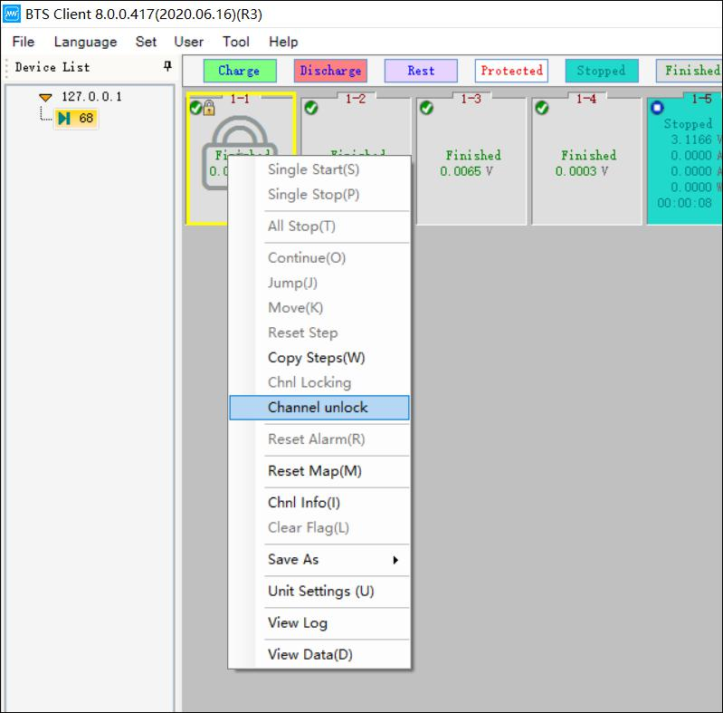
b. If you want to unlock the channels, just need to right click on the channels and choose ‘channel unlock’, then it will be unlocked.
Choose the channels need to unlock.
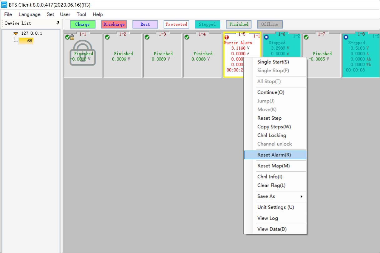
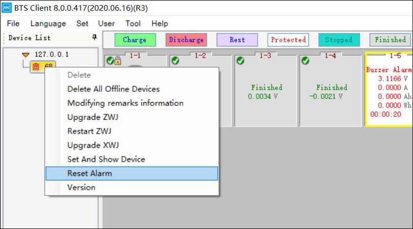
11. Reset alarm
1. Some channels were showing red exclamation mark due to safety settings triggered, in this kind of case, if you need to clear the warning, then right click on the channels and choose ‘reset alarm’, then the warning message will be gone. 2. If there are more than one channel were in warning status and you want to clear them all, then please right click on the mid machine ID, and choose ‘reset alarm’, then you can clear all the warning messages on all the channels under this mid machine.
12. Reset mapping
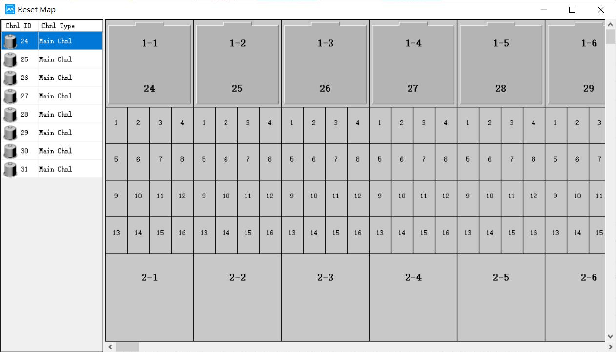
Set the mapping operation for the middle machine that has never been mapped, select the middle machine to be mapped (select in the device list, as shown in the figure below), click the right mouse button in the blank area on the right side of the interface → "reset mapping" → pop up " Settings mapping" interface.
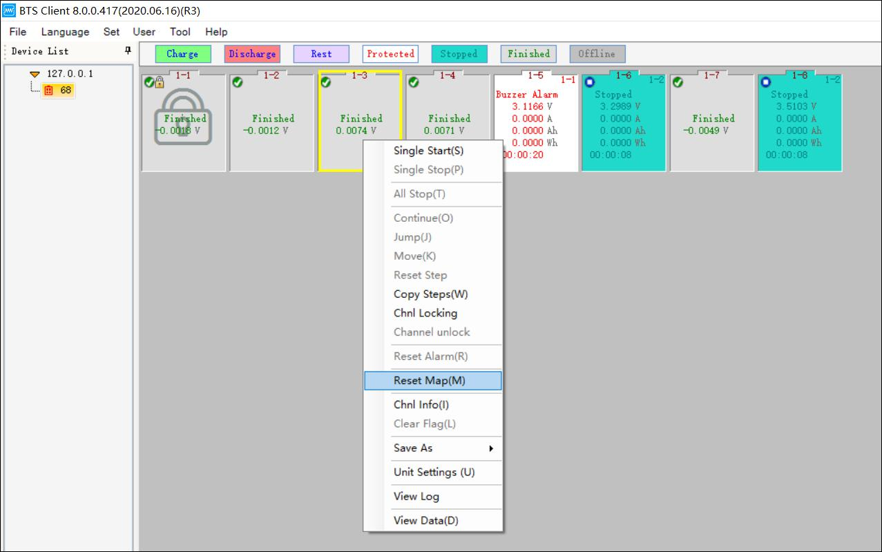
Figure 3.12.12 Channels mapping
Main channels mapping:
The main channel and the channel on the interface can be mapped arbitrarily, and the location of the main channel mapping is the location of the big box on the mapping interface. Select a channel and right-click with the mouse to select "Main Channel Default Mapping". There are five main settings: 1*8, 1*16, 1*24, 1*32 and custom. Choose one of the mapping methods and the system will map all the main channels, as shown in the figure below. If you want to cancel a mapping channel, click the right mouse button on the channel and select "Cancel current channel"; if you want to cancel all mapping relationships, select "Clear All";
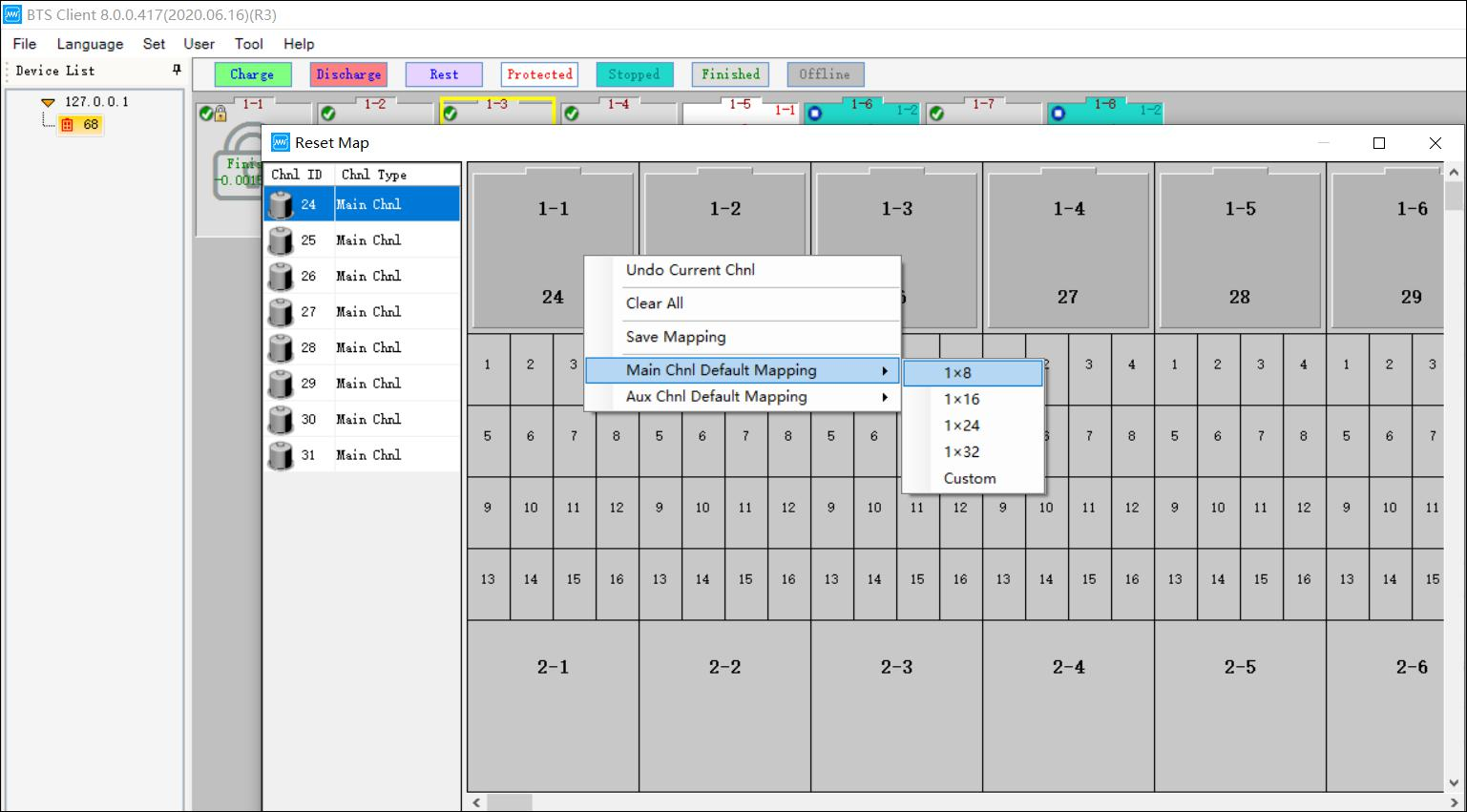
Figure 3.12.13 Channels mapping
Default mapping 1x8 means there’ll be 8 channels on each row, 1x16 means there’ll be 16 channels on each row. 1x24 means there’ll be 24 channels on each row, and 1x32 means there’ll be 32 channels on each row. 1x8 looks like the picture below.
And you can also customize mapping row*col, such as when you input 20 it means each row will have 20 channels. Maximum channels number on one row is 32, so if you input 32, then col will be 8 automatically.
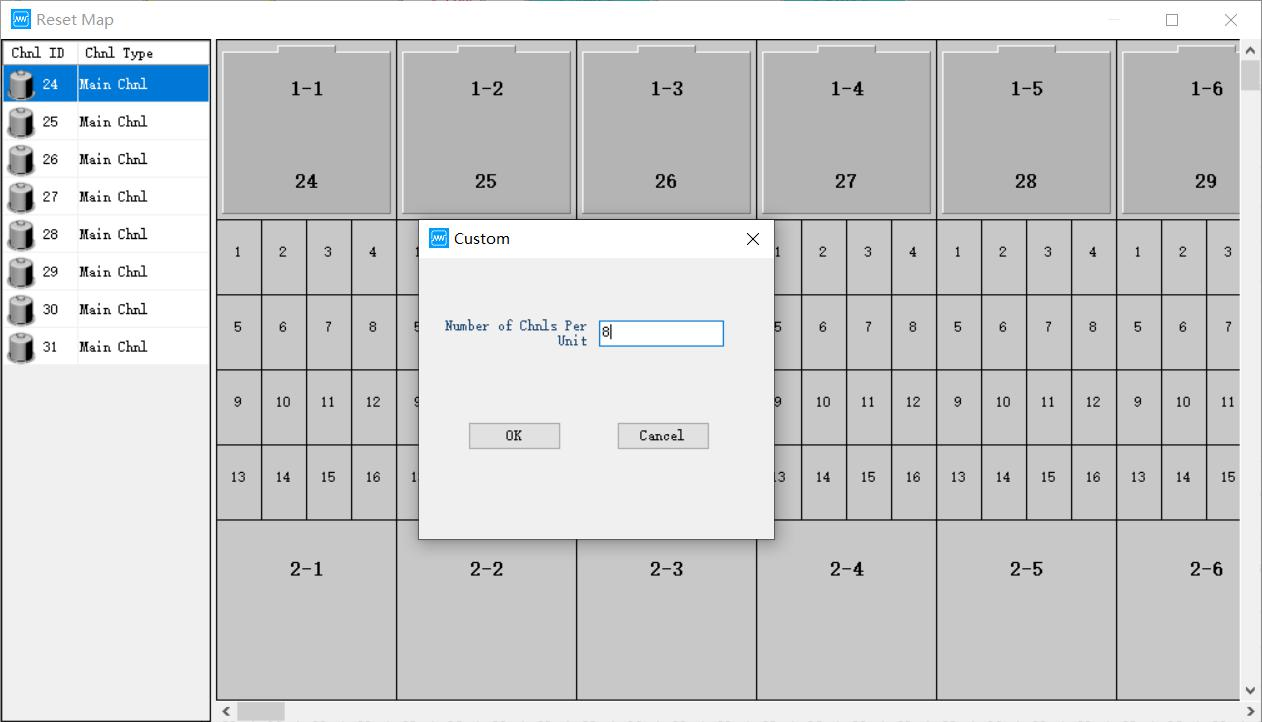
Figure 3.12.14 How many channels you want them to show in a row
Aux channels mapping: Right click on the main channel needs to add aux channels, select menu ‘aux channels mapping as default’ which means the aux channels will be mapped to main channels in average. After the mapping operation, right click again and choose ’save mapping’. Please refer to the picture below.
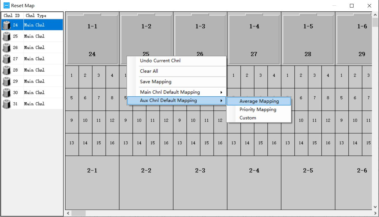
Figure 3.12.15 Aux channels mapping
Note: Yellow icon in above picture means channels not mapped yet, purple Icon means aux channels not mapped yet. And once the channels were mapped, the color will be gray, and the channels can’t be mapped again.
Note: The battery icon in front of the mapped main channel turns from yellow to gray, that is, it cannot be remapped; if you want to cancel the current mapped channel, click the right mouse button on the channel and select "Cancel current channel"; if you select "Clear all", cancel All mapped channels.
Note: If you want to cancel the mapping of an auxiliary channel, click the right mouse button on the auxiliary channel and select "Cancel current channel". To cancel all the mappings, select "Clear all". At this time, the mapping of all main channels and auxiliary channels will be cleared.
13. Channels copy
Function: When the channel ranges are the same, copy the step parameters of one channel to another or multiple channels. Operation method:
1. Select the target channel;
2. Right-click → "Channel Copy" to enter the channel copy interface, as shown in the figure below;
3. Click "Select Channel" in the lower right corner of the interface to enter the channel selection interface;
4. Select the channel number to be copied.
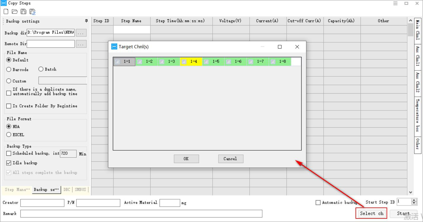
Figure 3.12.16 通道复制
14. Clear mark (reset channels)
Some functions can only be operated when the channel is completed. For protected or stopped channels, use the clear flag to change the channel status to completed. Operation method:
1. Select the target channel in the channel area
2. Right click "clear mark"
15. Units settings
According to the different test purposes of users, set the corresponding unit parameters to provide a flexible and simple setting platform. Operation method:
Right-click on the channel --> "Unit customization", select the unit to be set --> "OK", at this time, the data unit in the test data has been displayed according to the unit parameter set by the user, as shown in the following figure:
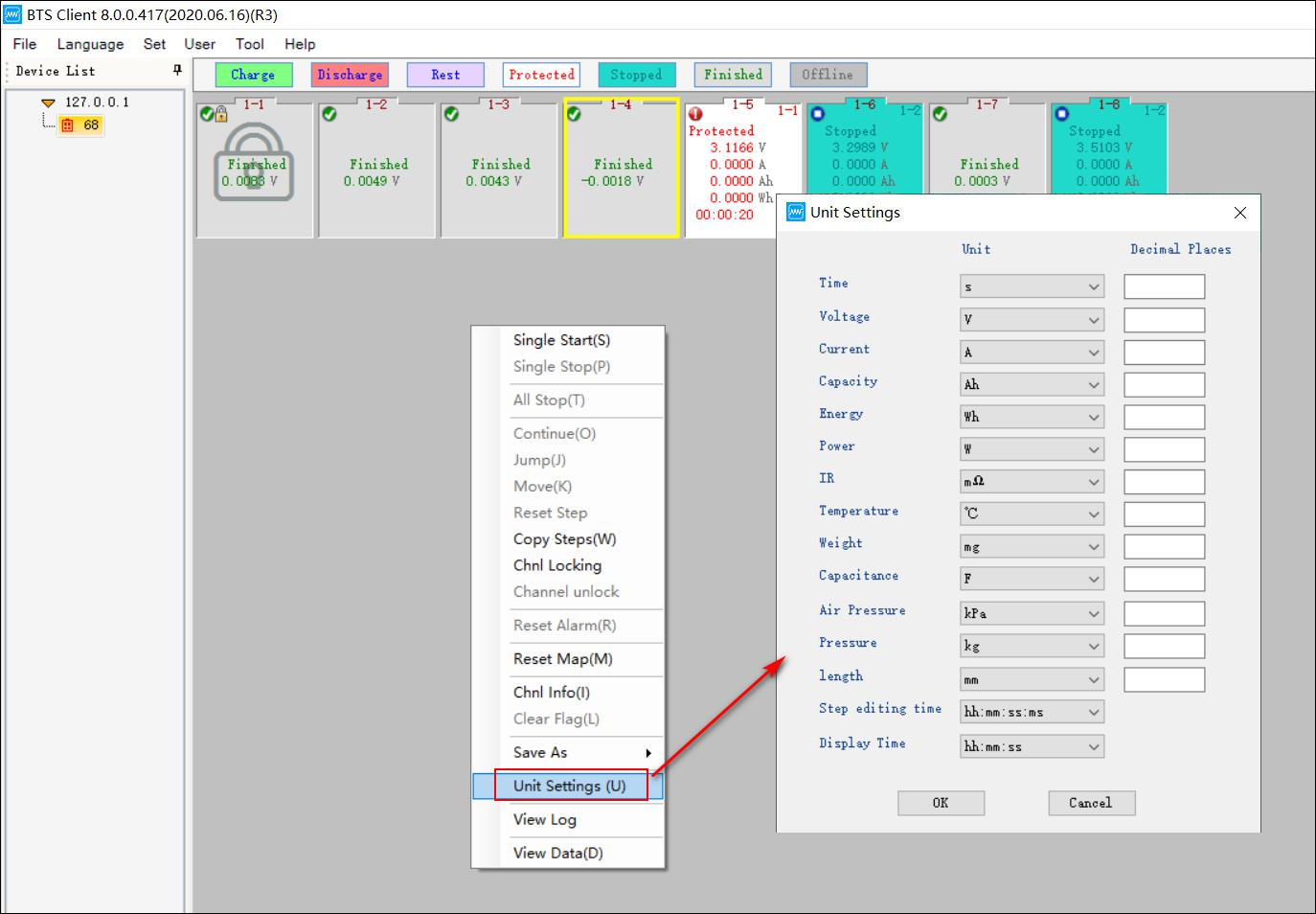
Figure 3.12.17 Units setting in BTS client
16. Check log
The BTS logs are included local logs and equipment logs. The local logs are user operations recorded by the client. The equipment logs are the channel test status changes recorded by the central computer and abnormal and prompt information during the test. Operation method:
Select the channel, right-click --> Log, and the log list will open as shown in the figure below:
Figure 3.12.18 BTS log view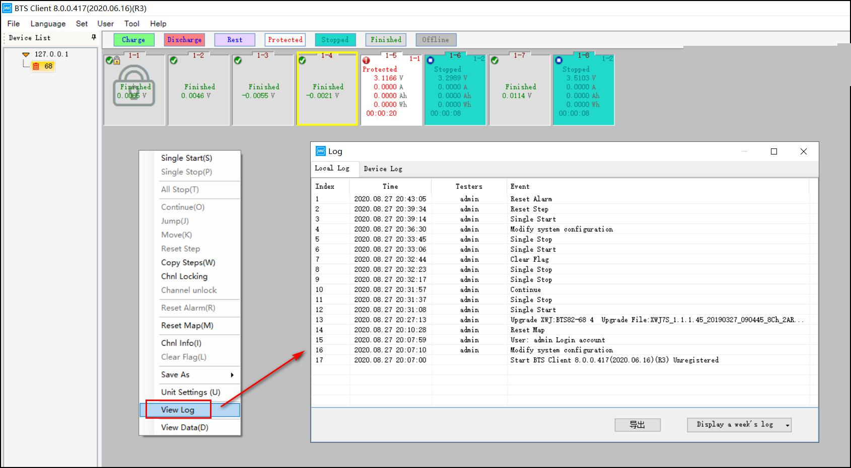
For local logs, you can double-click to view further information. For example, reset the mapping to view the mapping information before and after mapping, as shown in the following figure:
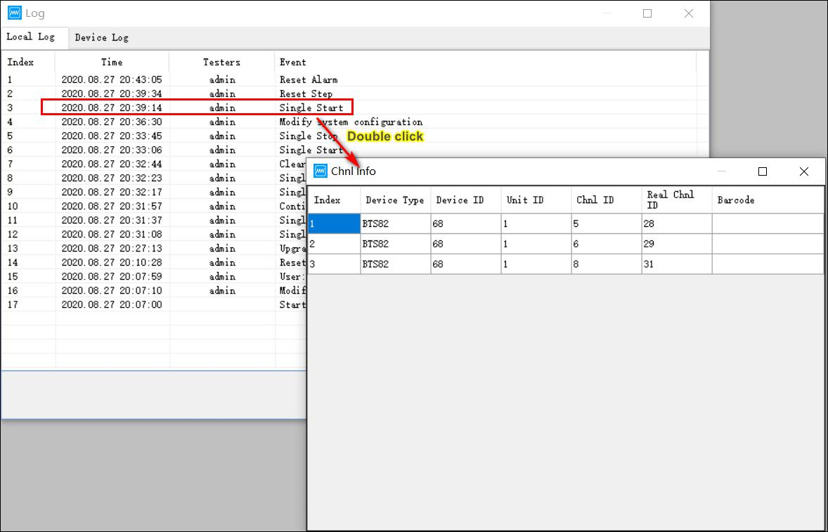
Figure 3.12.19 Double click to see log details
17. Channel data
Right-click → "Channel Data" to open the test data of the selected channel. Now you can analyze the corresponding channel test data, the interface is shown in the figure below, click icon
 , then the curve setting interface will appear. Under the "Curve Setting" interface, select the parameters represented by the X coordinate axis and the Y1 and Y2 coordinate axes. The default parameter settings are: X means "time", Y1 means "empty", Y2 means "empty", Y3
means "empty", Y4 means "empty", and then click the color under the label attribute
 then you can set up the color of the curves in the graph area. There are also other short-cut function on the tool bar, such as
  curves comparison,
  Data filter,
  Cycle layer data
expand,
 Steps layer data expand,
  Sampling layer data expand,
  Excel file export,
  DCIR calculation,
  Switch between data area and graph area.
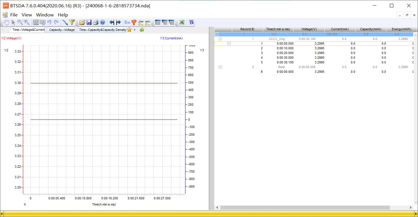
Figure 3.12.20 BTSDA interface
18. Channel data/Test data save as
Test data can be viewed through "Channel Data" and "Save Data As". Channel data operation method:
Click the right-click menu --> "Channel Data" to open the test data of the selected channel, and then analyze the data through the BTSDA software. How to save data as:
Click the right-click menu --> "Save Data As", select "Nda File" or "Excel File" and then select the export path, as shown in the following figure:
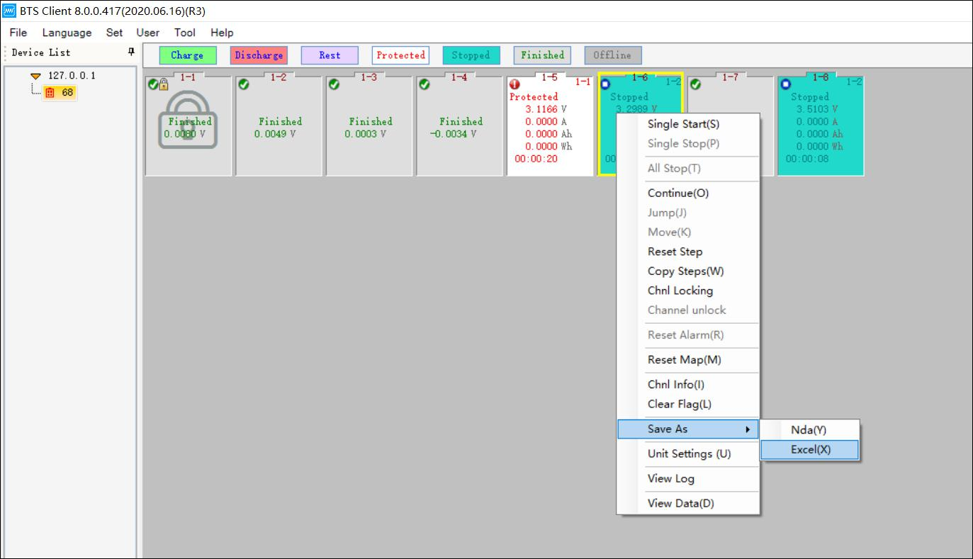
Figure 3.12.21 Save Neware NDA test data as other files format
The naming format of the data saved as file can be configured through the system settings, as shown in the figure below:
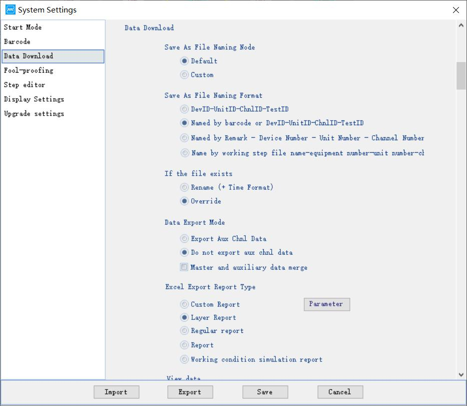
Figure 3.12.22 Save data as other formats
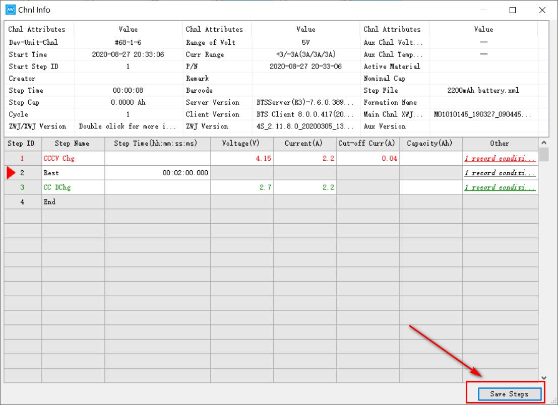
19. Channels information
Query the channel information to learn the detailed information of the selected channel. For example, you can view the current channel range, channel number, execution step status, software version and other detailed information,
 this icon indicating the currently executing step. Operation method:
1. Select the channel to be viewed (the selected mark means that the channel has a yellow frame);
2. Double-click or right-click "Channel Information". 1. The range information of dual-range equipment can be viewed through the battery range information on the channel information interface.
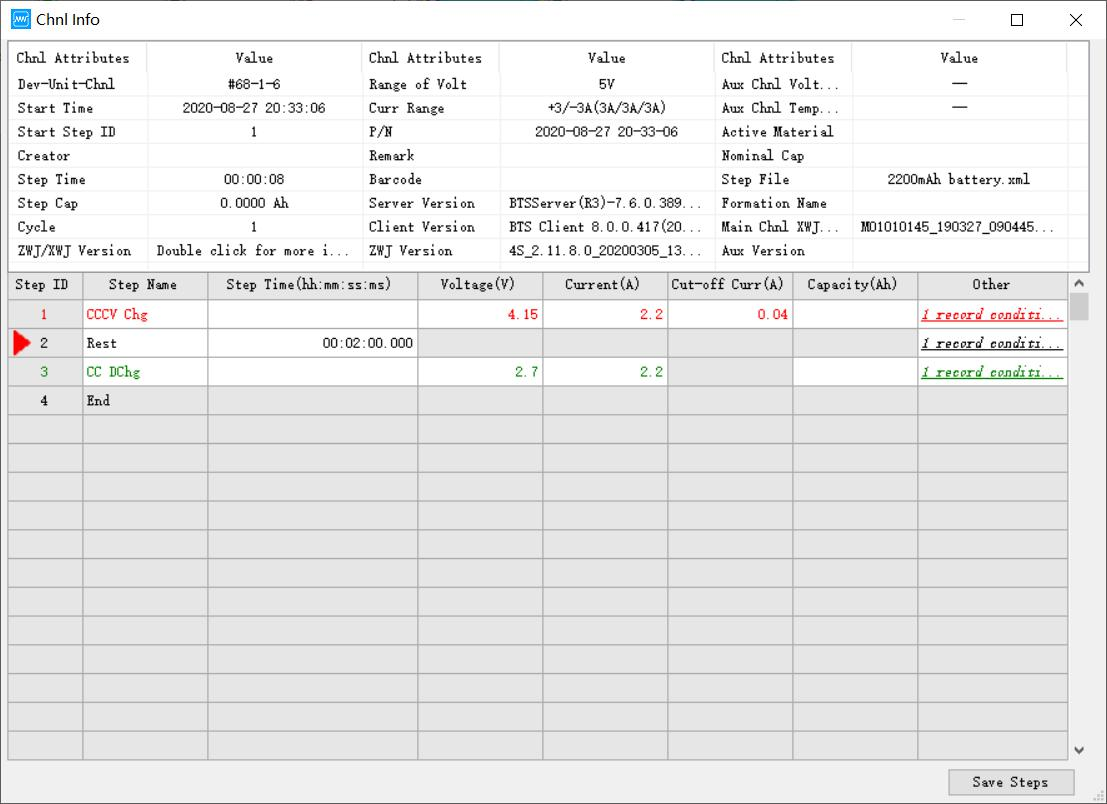
Figure 3.12.23 Check channel/profile info while running
In the "Channel Information" interface, double-click the "Middle Computer/Lower Computer Information" item in the channel attribute column to view more detailed information, as shown in the following figure:
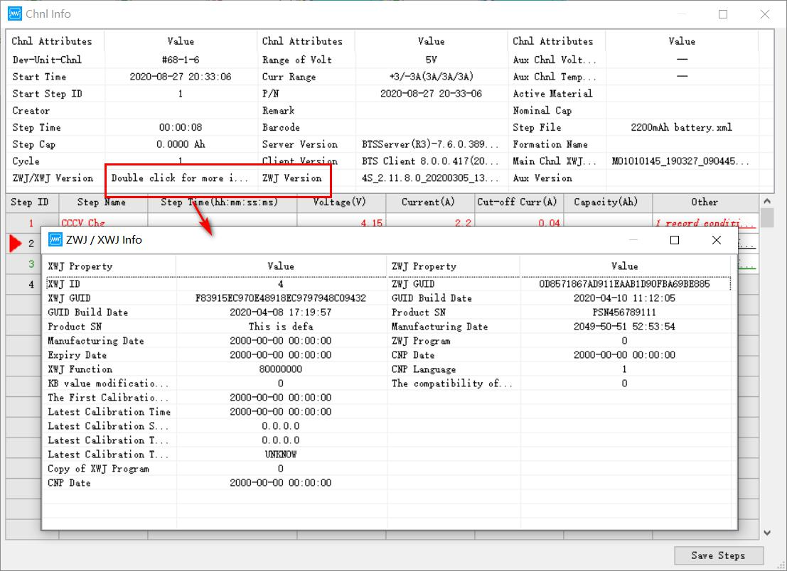
Figure 3.12.24 Check mid machine and tester info in detail
Click Save step to save the current step operating:
Click the save step button, and the save path will pop up and enter the step file name, as shown below:
-
List view
The channel state parameters are displayed in the form of a list, and the list display interface has the same functions as the channel graphic display interface for starting test, stopping test, and viewing data.
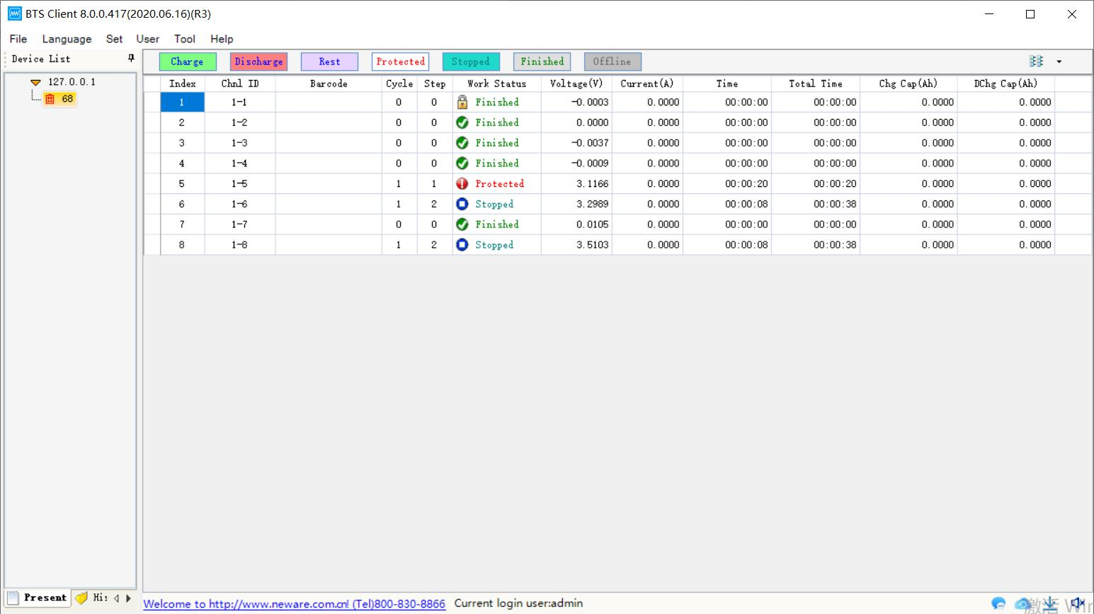
Figure 3.13.1 List view mode
1. Right menu functions
The list interface and the channel graphical interface have the same right-click menu function, as shown in the following figure:
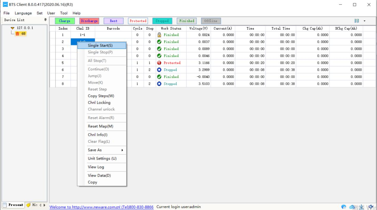
Figure 3.13.2 Right menu in the list view mode
2. Display parameters setting
List display can configure the column parameters to be displayed. Operation method:
1. Place the mouse on the head of the list;
2. Right click --> tick the parameters to be displayed.
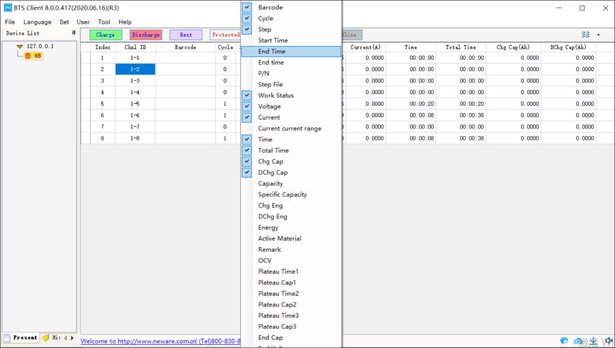
Figure 3.13.3 Configure the fields of list view mode
3. Bar-code input
The bar code entry function is displayed in the list. Right-click on the bar code entry column has: delete bar code, clear bar code, batch generate bar code, import bar code, export bar code, copy and other functions.
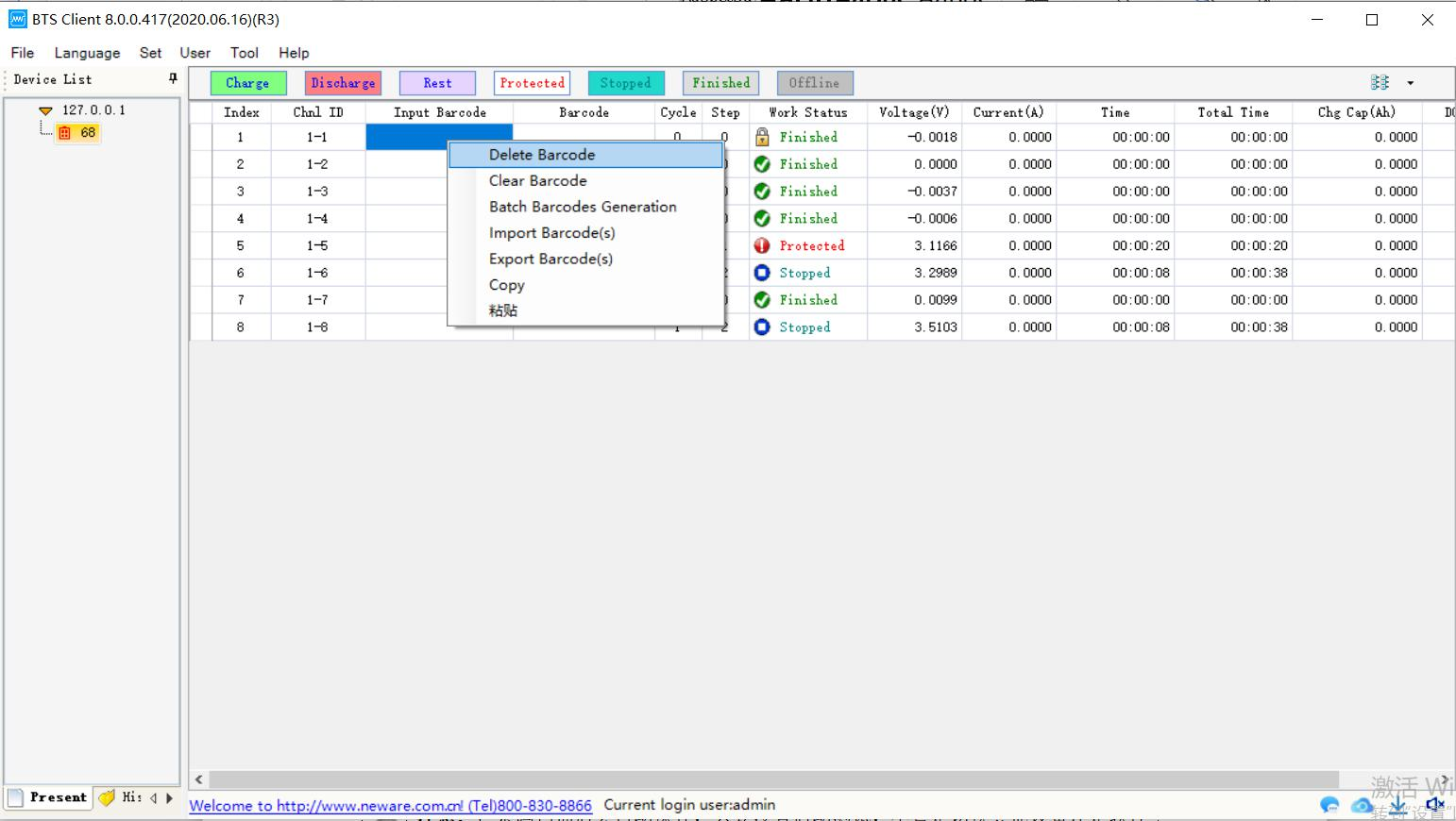
Figure 3.13.4 Input barcode
A. Input bar-code
① Manually enter or scan the bar code to start the test at a single point, and the bar code can be bound to the test data of the corresponding channel.
② Operation method:
③ In the list display, check "Enter barcode" (the newly entered barcode, which will be used in the next test) and "Barcode" (the barcode currently being tested);④ Select the channel number corresponding to the input bar code column, double-click the left mouse button to enter the input mode, and you can also use the code scanner;
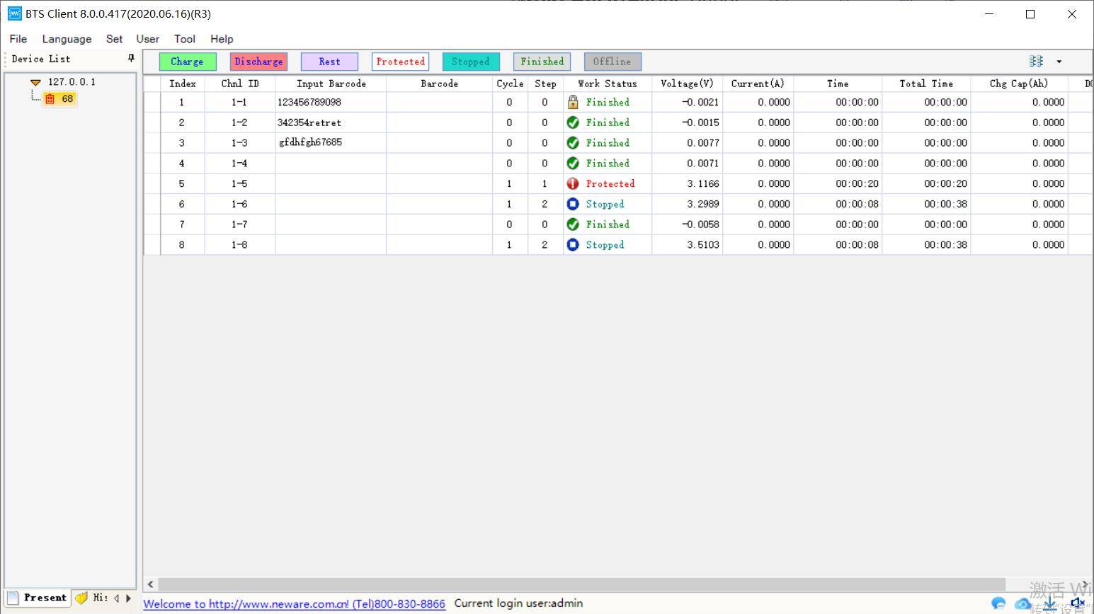
Figure 3.13.5 Barcode input
⑤ After entering the barcode manually, press Enter or scan the barcode with a barcode scanner, just make sure the input focus in in the correct barcode field;
⑥ The edit box automatically jumps to the next selected channel, and continues to scan the barcode;
⑦ Single-point start the corresponding channel after scanning is completed.
Note:
1. The barcode will be automatically saved after scanning. As long as the test is not
started, whether it is switching other devices or restarting the software, after switching
back, the scanned barcode still exists.
2. When selecting the "Enter barcode" menu, the display boxes of other columns cannot
be selected, otherwise the corresponding right-click menu will not be displayed.
3. The channel that has not selected "Enter barcode" cannot scan the barcode. If the
channel selected to enter the barcode is not continuous, after scanning the current
channel, it will skip to the next entered channel instead of the next channel number. 4."Barcode input" column can import and export barcode, "Barcode" column can export
barcode to txt format, this function is useful.
B. Delete
In the bar code entry column, select the channel which bar code needs to be deleted, right-click to delete the bar code then.
C. Clear/delete all
In the bar code entry column,right click to clear bar code,all bar codes will be cleared then.
D. Generate bar-code in a batch
For the convenience of testing, the software can generate continuous bar codes in batches. Operation method:
1. Select the edit box in the "Enter barcode" column;
2. Right click --> "Generate barcodes in batches";
3. Enter the initial barcode in the batch bar code generation window -->"OK".
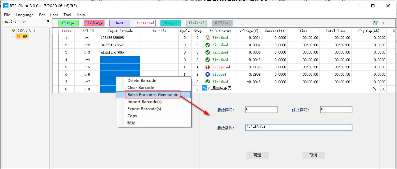
Figure 3.13.6 Generate barcodes in a batch
E. Import
Select the bar code entry column, select the channel to import the bar code, right-click and select import bar code file, after confirming, you can import the bar code file.
Note: Barcode input/import will start from the selected channel.
F. Export
Select input bar code or bar code column, right-click and select export bar code, the whole column bar code export will be saved as TXT file.
G. Copy
Select the bar code to be copied and right-click to copy.


Quick Links
CT-4008Q-5V100mA-124(4 Ranges)CT-4008Q-5V6A-164/S1(4 Ranges)CT-4008Tn-5V6A-164/S1 (3 Ranges)CT-4008Q-5V12A-204n/S1(4 Ranges)All-in-one Constant Temperature Chambers
-
HOT
-
ProductsBattery Testing EquipmentEnvironmental Test ChambersCalibration/ AUX/ BVIRCell Clamp & Cell TrayFormation & GradingBattery Assembly Equipment
-
SolutionsFor Material ResearchSmart LaboratoryFor 3C Digital CellFor EV PowerFor Energy StorageFor Prismatic Cell AutomationFor Pouch Cell AutomationFor Cylindrical Cell AutomationFor PACK Automation
-
Software
-
Service
-
About Us


 Global - English
